Solar Tracking for Terrestrial Solar Arrays with Variable Start and Stop Positions

a solar array and start position technology, applied in the direction of optical radiation measurement, navigation instruments, comonautical navigation instruments, etc., can solve the problem of continuous movement of the sun

Inactive Publication Date: 2010-04-29
SUNCORE PHOTOVOLTAICS
View PDF100 Cites 42 Cited by
  • Summary
  • Abstract
  • Description
  • Claims
  • Application Information

AI Technical Summary

Problems solved by technology

One difficulty, however, arises from the fact that the sun is continuously moving.

Method used


Image

  • Solar Tracking for Terrestrial Solar Arrays with Variable Start and Stop Positions
  • Solar Tracking for Terrestrial Solar Arrays with Variable Start and Stop Positions
  • Solar Tracking for Terrestrial Solar Arrays with Variable Start and Stop Positions

Examples


Embodiment Construction

Overview

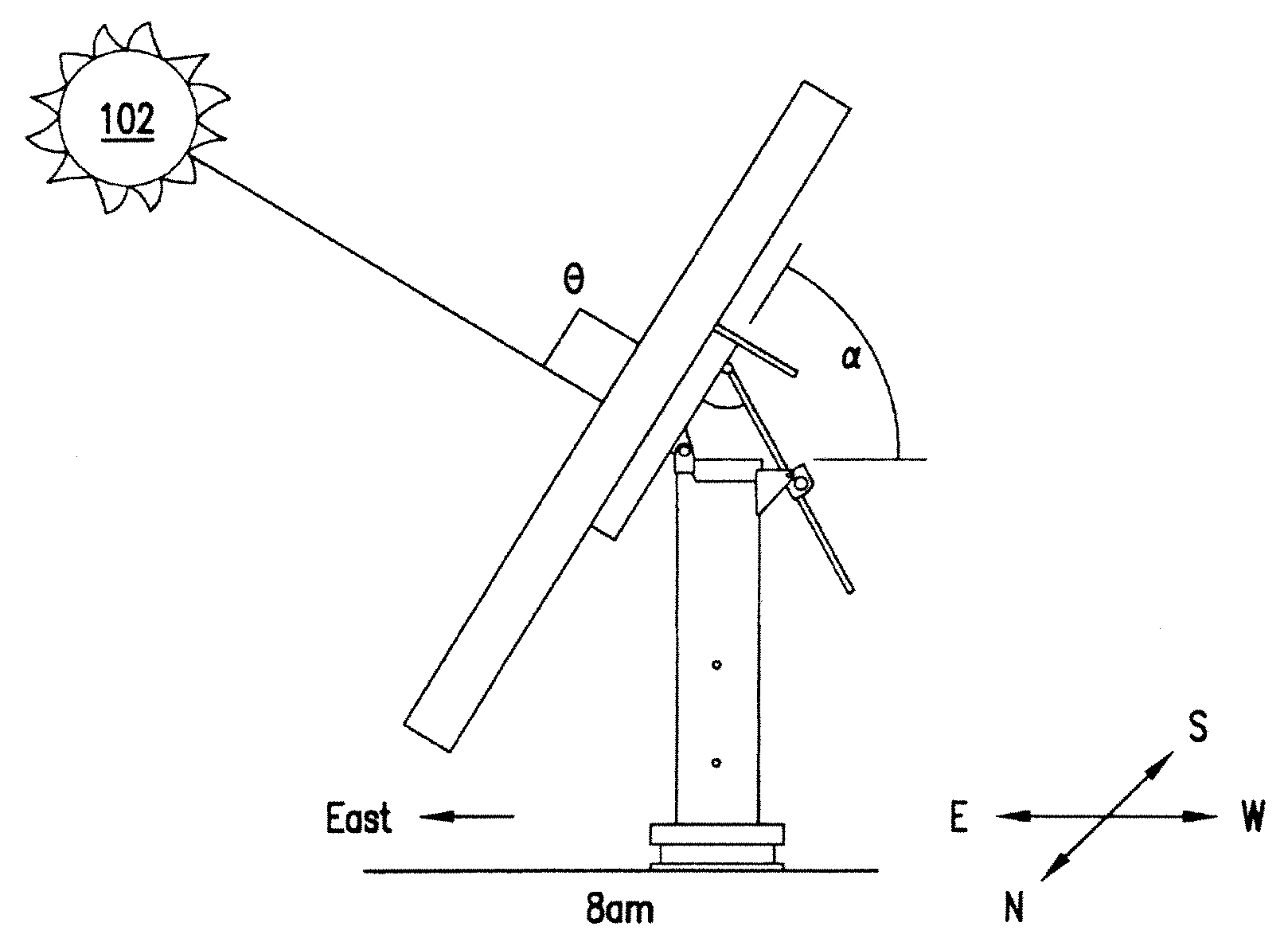
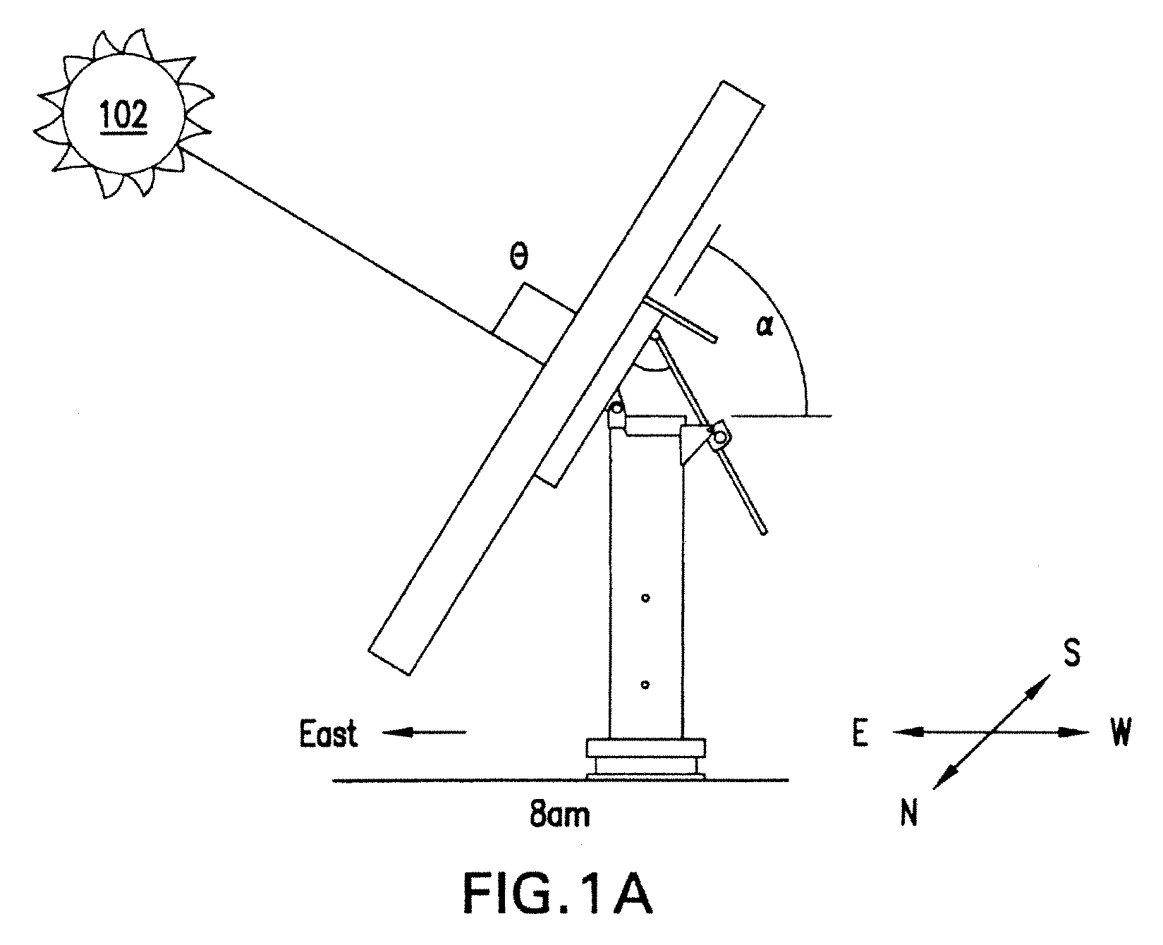
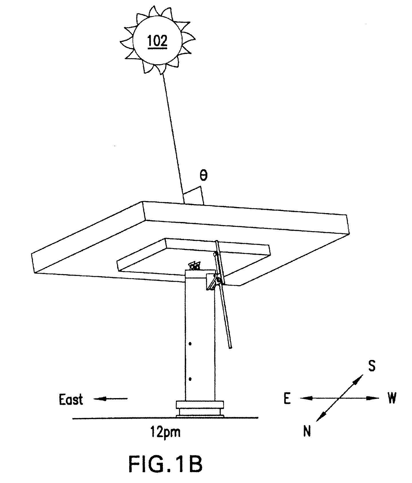
[0013]A terrestrial solar power system converts sunlight into electrical energy utilizing, e.g., multiple mounted arrays spaced in a grid over the ground. The array of solar cells has a particular optical size and is mounted for unitary movement on a cross-arm of a vertical support that tracks the sun. The array can include subarrays, sections, modules and / or panels.

[0014]The amount of power generated by the array is directly related to the amount of sunlight impinging upon the constituent solar cells. It is highly advantageous, therefore, to orient the array such that the plane of the array (of lenses and solar cells) is orthogonal to the incoming rays of the sun, and the power generation is maximized. To that end, a solar tracking mechanism is employed that ensures that the plane of concentrator lens results in a beam projected on the center of the respective solar cells in a continuous manner as the sun traverses the sky during the day, thereby optimizing the amount of su...


PUM


Abstract

An automated method causes a terrestrial solar cell array to track the sun. The solar cell system includes motors that adjust a position of the array along different respective axes with respect to the sun, wherein a first motor adjusts the inclination angle of the array relative to the surface of the earth and a second motor rotates the array about an axis substantially perpendicular to that surface. The method includes (a) using a software algorithm to predict a position of the sun at a future time; (b) using a computer model to determine respective positions for the motors corresponding to the solar cell array being substantially aligned with the sun at the future time; and (c) activating and operating the motors at respective particular speeds so that at the future time the solar cell array is substantially aligned with the sun. The future time may correspond to any time during operation. An initial future time may correspond to a start up time after sunrise at which point the solar cell is to begin tracking the sun.

Description

CROSS-REFERENCE TO RELATED APPLICATIONS[0001]This disclosure is related to co-owned U.S. Pat. No. 7,381,886; patent application Ser. No. 12 / 024,489 filed on Feb. 1, 2008; and patent application Ser. No. 12 / 131,556 filed on Jun. 2, 2008. The present application is a continuation-in-part of U.S. application Ser. No. 12 / 258,253, entitled “Solar Tracking for Terrestrial Solar Arrays,” filed on Oct. 24, 2008, which is incorporated herein by reference in its entirety.TECHNICAL FIELD[0002]This disclosure relates to solar tracking for terrestrial solar cell arrays.BACKGROUND[0003]This disclosure relates generally to solar tracking for use with one or more terrestrial solar cell arrays that convert sunlight into electrical energy. Accurate solar tracking is necessary because the amount of power generated by a given solar cell is related to the amount of sunlight that impinges on it. In an array, therefore, it is advantageous to optimize the amount of sunlight that impinges on each constituen...

Claims


Application Information

Patent Timeline
Patent Type & Authority Applications(United States)
IPC IPC(8): G01J1/20F24S50/20
CPCF24J2/38F24J2/4607F24J2/523F24J2/542F24J2200/04Y02E10/47H01L31/0522H01L31/052H02S20/00H01L31/054H01L31/0543H01L31/0422Y02E10/52H02S20/32H02S20/23H02S20/10F24S50/20F24S25/10F24S30/452F24S2201/00F24S40/00Y02B10/10
Inventor SHERMAN, JAMES
Owner SUNCORE PHOTOVOLTAICS
Why Eureka
Try Eureka