Method for identifying 3-d location of gamma interaction and flat panel gamma imaging head apparatus using the same

a technology of gamma interaction and imaging head, which is applied in the field of location determination method and sensing apparatus, can solve the problems of blur images, poor quality, and increased possibility of parallax occurrence of scintillation, and achieve the effect of improving quality

Active Publication Date: 2010-04-29
INST NUCLEAR ENERGY RES ROCAEC
View PDF1 Cites 9 Cited by
  • Summary
  • Abstract
  • Description
  • Claims
  • Application Information

AI Technical Summary

Benefits of technology

[0010]The present invention provides a method for identifying a location (along the crystal long axis) of gamma interaction capable of choosing from

Problems solved by technology

However, on the conventional imaging detector, when the incident angle θ of the gamma ray increases, the possibility of parallax occurrence of scintillation also increases because of the high energy of the gamma ray and the small size of the scintillator crystals.
The error is referred to as the paral

Method used


Image

  • Method for identifying 3-d location of gamma interaction and flat panel gamma imaging head apparatus using the same
  • Method for identifying 3-d location of gamma interaction and flat panel gamma imaging head apparatus using the same
  • Method for identifying 3-d location of gamma interaction and flat panel gamma imaging head apparatus using the same

Examples


Embodiment Construction

[0030]The present invention can be exemplified but not limited by various embodiments as described hereinafter.

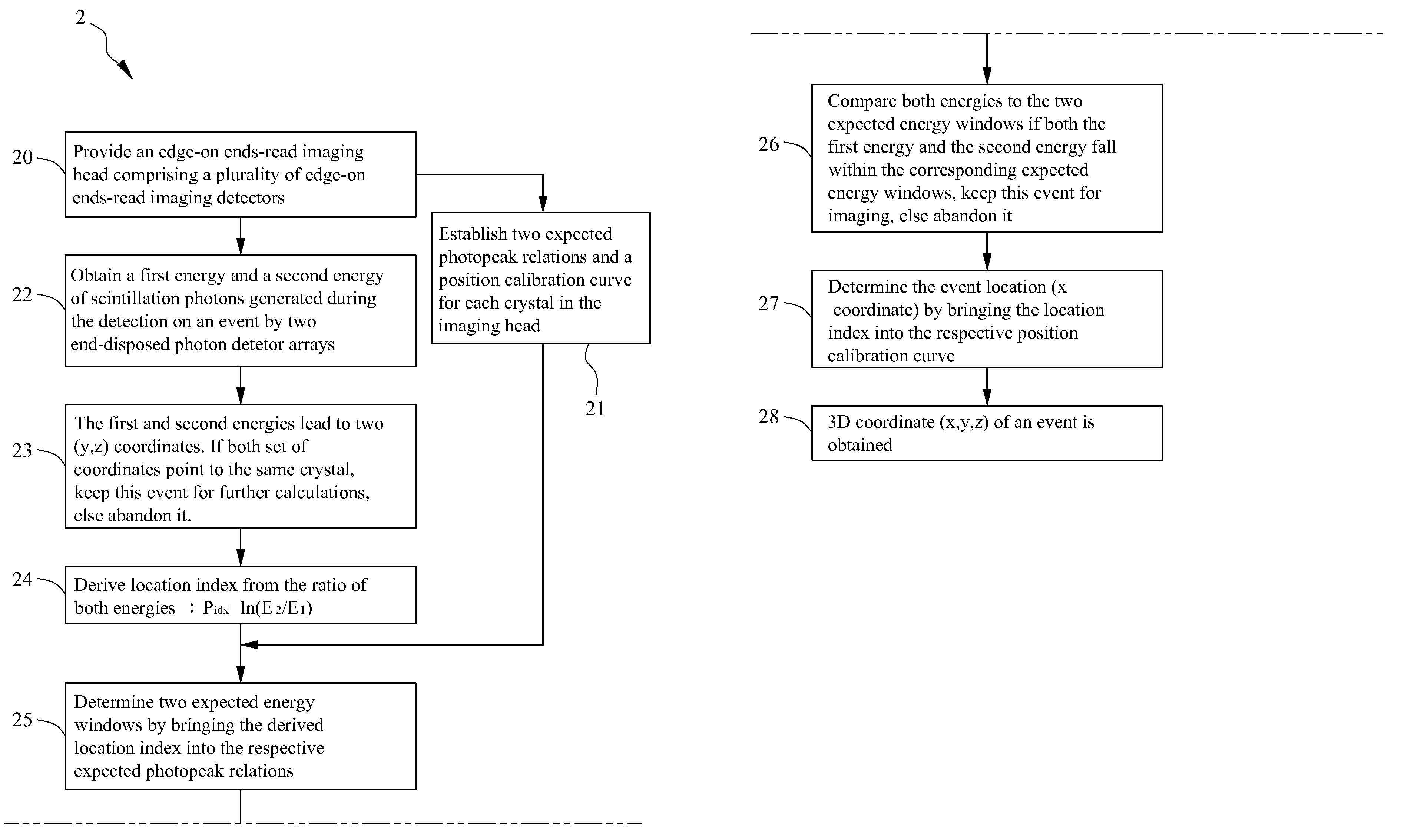
[0031]Please refer to FIG. 4, which is a flowchart of a method for identifying an event location of gamma interaction according to one embodiment of the present invention. In the present embodiment, the method 2 comprises steps as described herein. Firstly, step 20 is performed to provide an edge-on ends-read imaging head apparatus as shown in FIG. 5. The edge-on ends-read imaging head apparatus 3 comprises a plurality of edge-on ends-read imaging detectors 30. Each edge-on ends-read imaging detector 30 has a sensor array 300 and a pair of photon detector arrays 301 respectively coupled to both ends of the sensor array 300. The plurality of edge-on ends-read imaging detectors 30 are arranged as a sensing flat panel. Each sensor array 30 comprises a plurality of thin long (longer than 6 cm) sensors 3000 in a 2-D rectangular array. The sensors are scintillator blocks comprisi...


PUM


Abstract

The present invention provides a method for identifying a 3-D event location of a gamma interaction for enhancing the precision of event location determination and improving the practicability of an edge-on ends-read imaging detector. The method establishes two expected photopeak relations and a mapping table for every unit in the sensor array before imaging. In real practice, two sensing values with respect to the energy of scintillation photons generated during the detection on an event are obtained by the edge-on ends-read imaging detector. Furthermore, two energy windows corresponding to each sensing value are determined according to the corresponding expected photopeak relations. If both the two sensing values fall within the corresponding energy windows respectively, the event location along the long axis of sensor array is determined according to the sensor values with respect to the mapping table mentioned above.

Description

1. FIELD OF THE INVENTION[0001]The present invention generally relates to a location determination method and a sensing apparatus and, more particularly, to a method for identifying a location of gamma interaction where scintillation light is generated and a flat panel gamma imaging head apparatus.2. BACKGROUND OF THE INVENTION[0002]Nuclear medicine imaging modalities have become a medical specialty using radioisotopes for diagnosis, treatment, and research. To improve the capability in detecting dread disease (such as cancer) so that the doctor is able to make rapid and correct decisions to perform diagnosis or treatment, nuclear medicine has attracted tremendous attention in some industrialized nations.[0003]The modalities obtain the images regarding the pharmaceutical and bio-functional distributions in the tissues by picking up and processing the energy detected from emitted gammas within the tissues so that the doctor can perform diagnosis and treatment according to the images....

Claims


Application Information

Patent Timeline
IPC IPC(8): G01D18/00G01T1/20
CPCG01T1/00
Inventor LIANG, HSIN-CHIN
Owner INST NUCLEAR ENERGY RES ROCAEC
Why Eureka
Try Eureka