Light source module and backlight light source

a technology of light source module and backlight light source, which is applied in the direction of coupling device connection, instruments, lighting support devices, etc., can solve the problems of reducing the yield of backlight light source, and increasing the number of components

Inactive Publication Date: 2010-04-29
SHARP KK
View PDF14 Cites 36 Cited by
  • Summary
  • Abstract
  • Description
  • Claims
  • Application Information

AI Technical Summary

Benefits of technology

[0024]According to the above-described embodiment, by letting the light emitted from the backlight light source enter the diffusion plat

Problems solved by technology

This may increase the number of LEDs mounted on a single mounting substrate, diminishing the yields of backlight light source.
However, backlight light sources in which a plurality of light source modules are

Method used


Image

  • Light source module and backlight light source
  • Light source module and backlight light source
  • Light source module and backlight light source

Examples


first embodiment

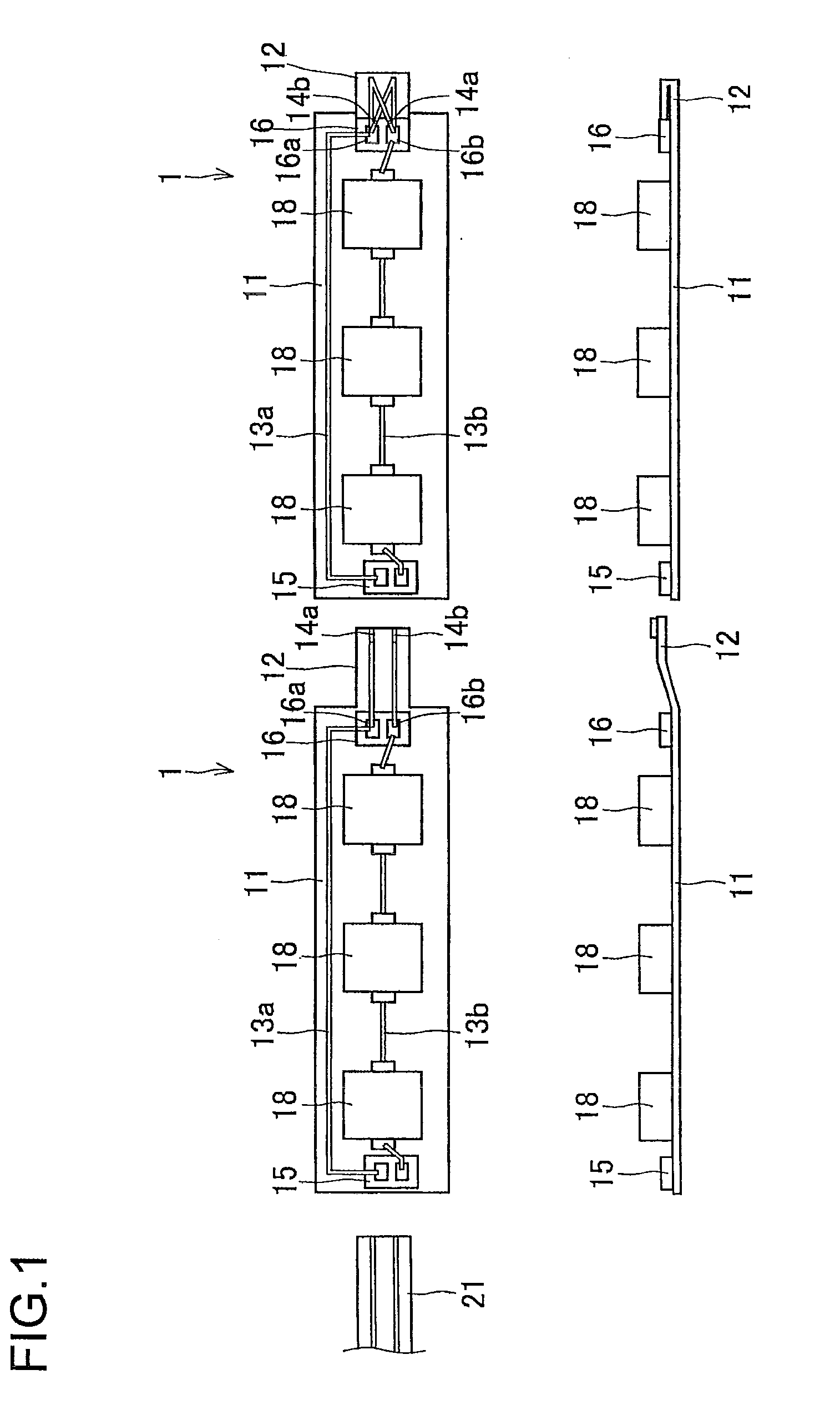
[0043]FIG. 1 is a diagram schematically showing a light source module as the present invention, showing the light source module in a plan view and a side view put together. FIG. 1 shows two light source modules before they are connected to each other.

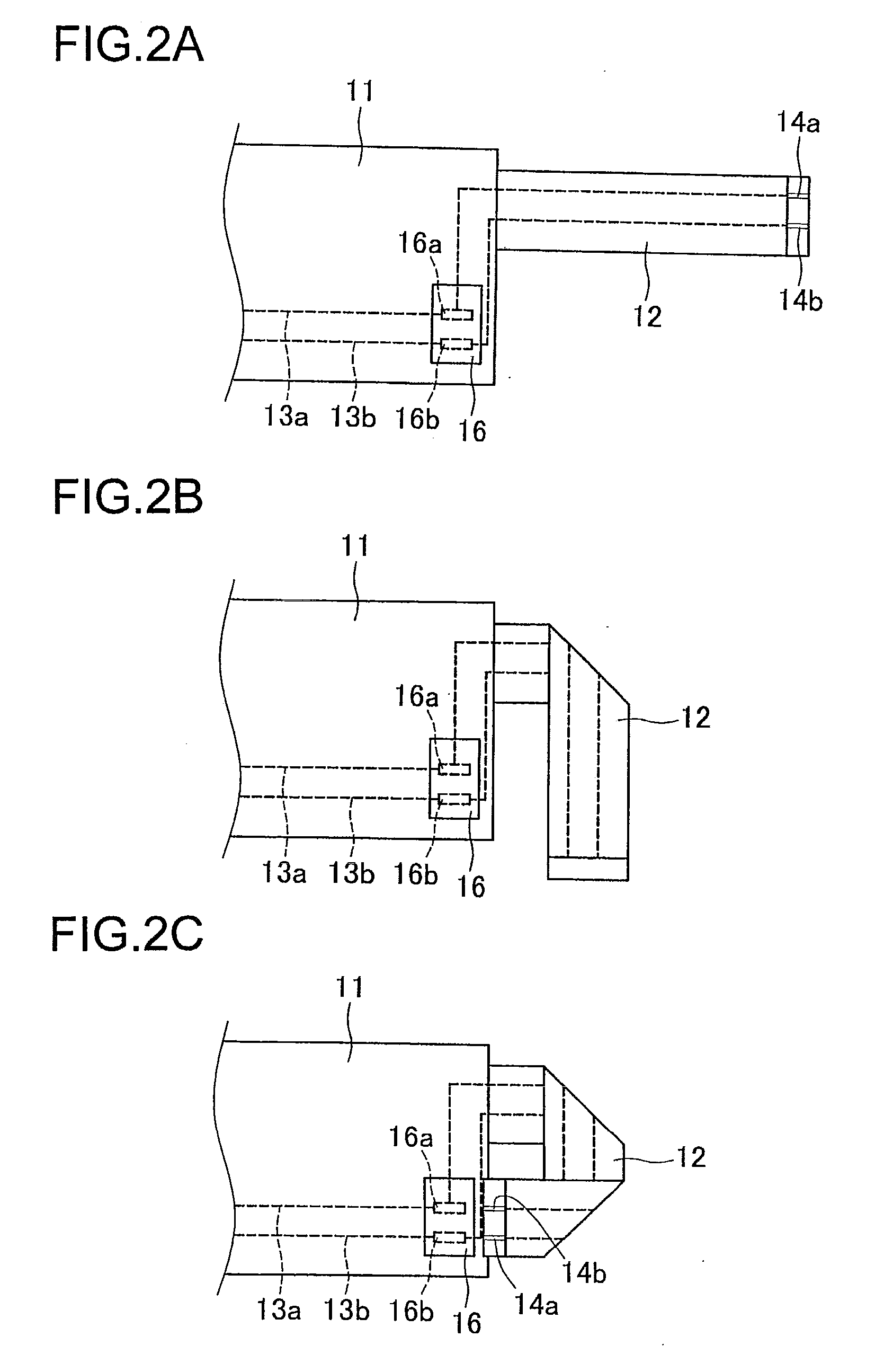
[0044]As shown in FIG. 1, the light source module 1 is provided with: a mounting substrate 11 and a connection substrate 12 formed integral with each other; two conductors 13a and 13b formed on the mounting substrate 11 and the connection substrate 12; terminals 14a and 14b located in a tip part of the connection substrate 12 and formed at one end of the two conductors 13a and 13b respectively; a first connector 15 connected to the other end of the conductors 13a and 13b; and a second connector 16 connected to the one end of the conductors 13a and 13b. On the mounting substrate 11, three LEDs 18, 18, 18 are mounted and each of them is connected to a single conductor 13b in series. The LEDs 18 are all white light emitting LEDs.

[0045]The ...

second embodiment

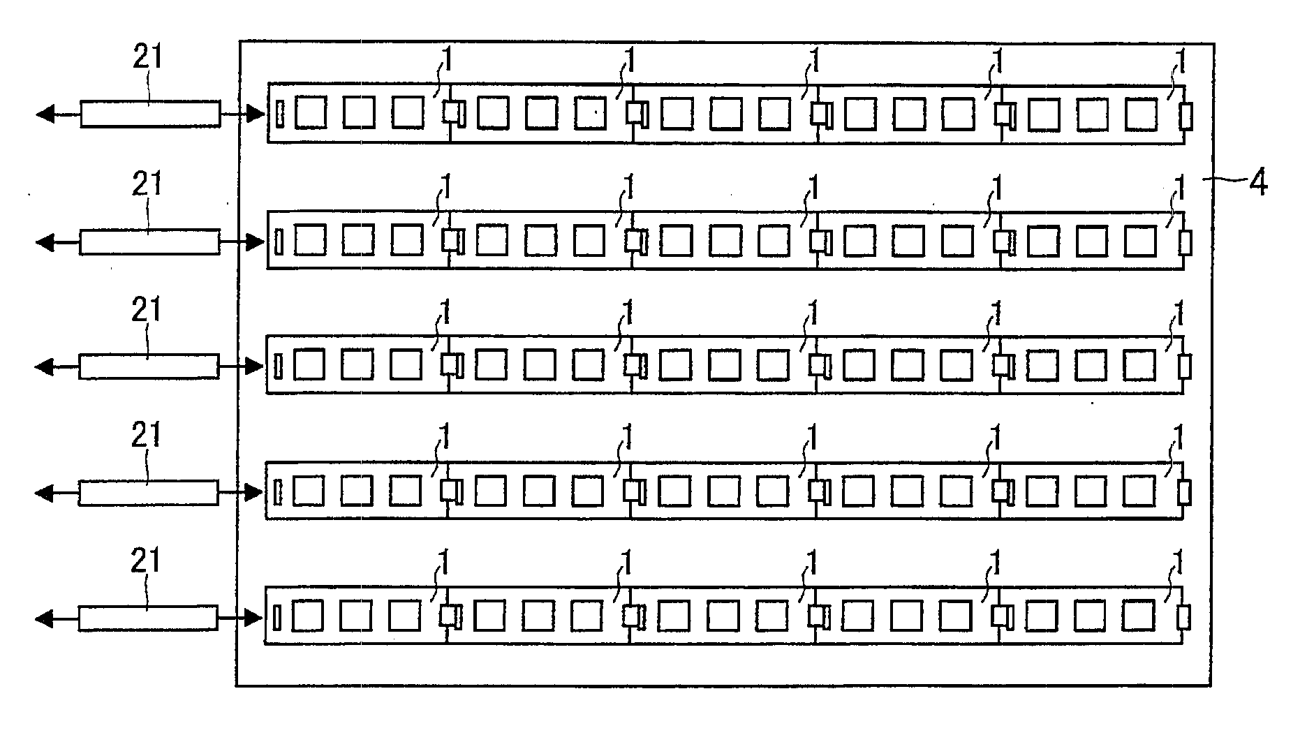
[0061]Also in the backlight light source according to this embodiment, as in the backlight light source the plurality of light source modules 1 are linearly connected, with the connection substrate 12 of one light source module 1 connected to the first connector 15 of the next, and in addition the connection substrate 12 of the light source module 1 at the terminal end is connected to the second connector 16. The first connector 15 of the light source module 1 located at the starting end of each row is connected to an LED driver circuit via an FFC 21.

[0062]Also in the backlight light source according to this embodiment, by adjusting the positions of the plurality of light source modules according to the light amount of the LEDs 18 of the light source modules, it is possible to achieve a proper distribution of the light amount in the entire diffusion plate 5.

[0063]Although the plurality of LEDs 18 of the light source module 1 are all the same white light emitting LEDs in the embodim...


PUM


Abstract

A light source module (1) is constituted by forming lines (13a, 13b) on a mounting substrate (11) and a connection substrate (12) integrally formed of a flexible material, and mounting a first connector (15), a second connector (16), and a plurality of LEDs (18) on the substrates. The connection substrate of one of adjoining light source modules is connected with the first connector (15) of the other light source module, thereby connecting a plurality of light source modules (1) linearly. In the light source module (1) at the end, terminals (14a, 14b) of the connection substrate (12) are connected with the second connector (16) while being reversed, thereby interconnecting two lines (13a, 14b). A plurality of light source modules (1) can thereby be connected without using a separate component such as a wire harness.

Description

TECHNICAL FIELD[0001]The present invention relates to a light source module and a backlight light source that are employed in, for example, a liquid crystal display device.BACKGROUND ART[0002]Conventionally, as backlight light sources for liquid crystal display devices, there are known backlight light sources that have a plurality of LEDs (light emitting diodes) mounted in a matrix on a mounting substrate and that are disposed on the back surface side of a liquid crystal display panel (see, e.g., Patent Document 1). As mounting substrates for such backlight light sources, aluminum substrates and glass epoxy substrates are widely used; typically, a single substrate roughly the same size as the liquid crystal display panel is used.[0003]These days, as liquid crystal display devices are made increasingly large, mounting substrates for backlight light sources are made accordingly large. This may increase the number of LEDs mounted on a single mounting substrate, diminishing the yields o...

Claims


Application Information

Patent Timeline
IPC IPC(8): G02F1/13357F21S4/00
CPCF21K9/00H01R23/667H01R25/162H05K1/118H05K1/142H05K1/147F21Y2101/02H05K1/189H05K2201/055H05K2201/058H05K2201/10106H05K2201/10189H05K1/148F21Y2115/10H01R12/78
Inventor HAMADA, TETSUYA
Owner SHARP KK
Why Eureka
Try Eureka