Vibration suppressing method and vibration suppressing device for machine tool

a technology of vibration suppressing device and machine tool, which is applied in the direction of electric programme control, program control, instruments, etc., can solve the problems of shortening the tool life, deteriorating the machining surface, and affecting the operation of the machine tool

Active Publication Date: 2010-04-29
OKUMA CORP +1
View PDF28 Cites 66 Cited by
  • Summary
  • Abstract
  • Description
  • Claims
  • Application Information

AI Technical Summary

Benefits of technology

[0023]With the above configuration of the third aspect of the present invention, in addition to the above advantageous effects, an appropriate optimum rotation speed can be obtained in accordance with a change in the machining state by correcting the approximation formula or the modal parameter per se where necessary based on the actual machining data.

Problems solved by technology

In an end mill machining, chatter vibration occurs in accordance with machining conditions such as a cutting amount and a rotation speed of a rotary shaft, which will result in deterioration of a machining surface.
The chatter vibration will damage the tool, resulting in shortening of the tool life.
Therefore, the method disclosed in Patent document 2 causes an error in the optimum rotation speed by the phase difference.
However, the vibration suppressing method as disclosed in Patent document 1 requires an expensive impulse device, and an excitation using the impulse device requires advanced techniques and great care.
Further, in most cases, the natural frequency measured in advance of machining with the impulsive excitation or the like tends to differ from the natural frequency during the actual machining, and therefore it is difficult to accurately obtain the optimum rotation speed based on this method.
For this reason, according to the vibration suppressing method as disclosed in Patent document 2 in which the measured chatter frequency is used as it is, it is difficult to accurately obtain the optimum rotation speed.
Although the phase information and the rotation speed corresponding to a certain chatter frequency can be calculated based on the method as disclosed in Non-patent document 2, it is very difficult to perform inverse transformation using this calculating formula.
As a result, from a practical standpoint of view, it is difficult to analytically obtain the chatter frequency corresponding to the intended phase information.

Method used


Image

  • Vibration suppressing method and vibration suppressing device for machine tool
  • Vibration suppressing method and vibration suppressing device for machine tool
  • Vibration suppressing method and vibration suppressing device for machine tool

Examples


Embodiment Construction

[0037]With reference to the accompanying drawings, one preferred embodiment of the present invention will be described in detail.

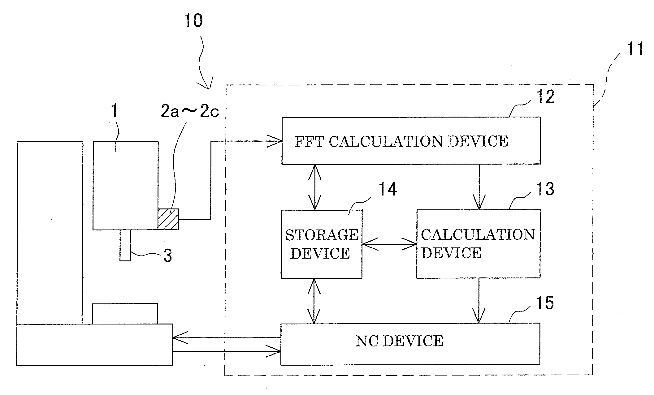
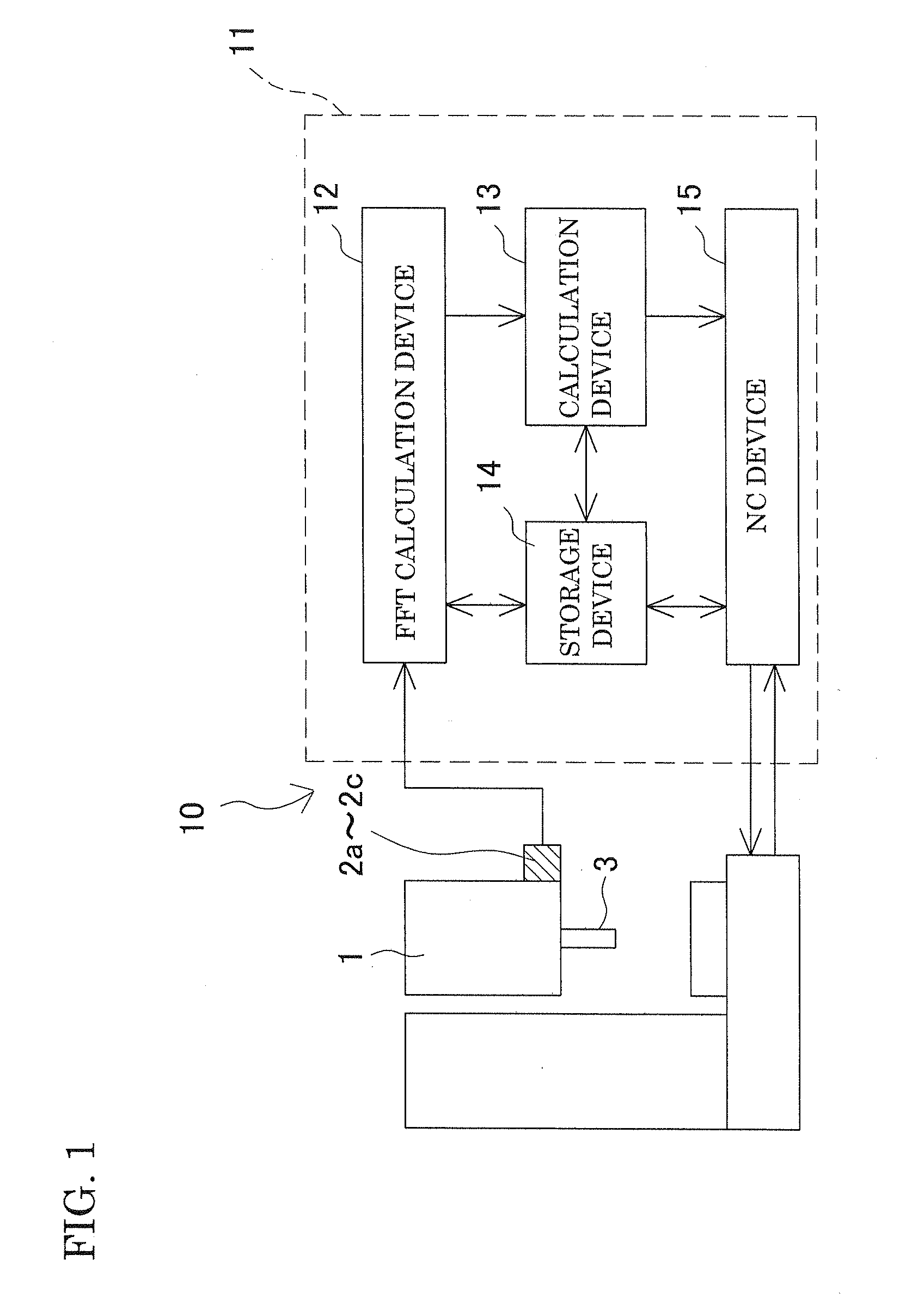
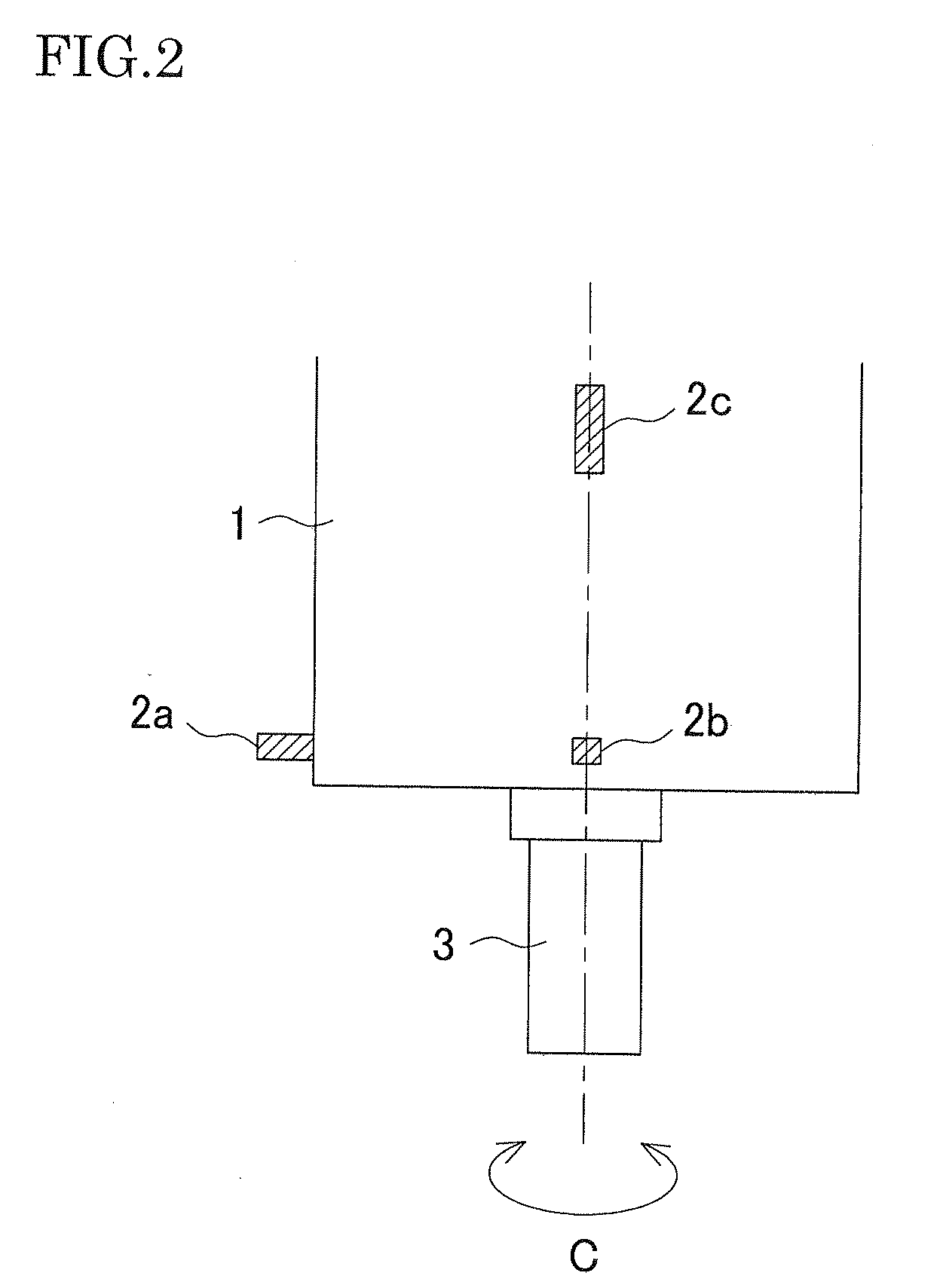
[0038]Among the attached drawings, FIG. 1 is a block diagram of a vibration suppressing device according to one embodiment of the present invention, FIG. 2 is a side view of a main spindle housing of a machine tool, and FIG. 3 is a top view of the main spindle housing as seen from an axial direction of the main spindle.

[0039]A vibration suppressing device 10 is configured to control chatter vibration generated at a main spindle 3 as a rotary shaft that is provided on a main spindle hosing 1 in such a manner as to be rotatable around a C-axis. The vibration suppressing device 10 comprises vibration sensors 2a-2c as vibration detecting units configured to detect time-domain vibrational acceleration (vibrational acceleration on a time axis) which occurs on the main spindle 3 while rotating, and a controller 11 configured to control the rotation speed of the m...


PUM

PropertyMeasurementUnit
frequencyaaaaaaaaaa
chatter frequencyaaaaaaaaaa
timeaaaaaaaaaa

Abstract

A vibration suppressing method and a vibration suppressing device are disclosed. After a tool is attached to a main spindle, a modal parameter of the tool or a workpiece is computed. Thereafter, a relation between chatter frequency and phase difference is calculated as an approximation formula based on the obtained modal parameter and machining conditions. If chatter vibration occurs after initiation of the machining, a chatter frequency corresponding to a target phase difference is obtained using the approximation formula, and based on the obtained chatter frequency, the number of tool flutes and the main spindle rotation speed, the optimum rotation speed is calculated. The rotation speed of the main spindle is then changed in accordance with the obtained optimum rotation speed.

Description

[0001]This application claims the benefit of Japanese Patent Application Number 2008-277139 filed on Oct. 28, 2008, the entirety of which is incorporated by reference.BACKGROUND OF THE INVENTION[0002]1. Field of the Invention[0003]The present invention relates to a vibration suppressing method and a vibration suppressing device for a machine tool which is provided with a rotary shaft for rotating a tool or a workpiece to machine the workpiece, and more particularly to a vibration suppressing method and a vibration suppressing device for preventing deterioration of a machining surface and shortening of tool life due to chatter vibration generated during machining of the workpiece.[0004]2. Description of Related Art[0005]In an end mill machining, chatter vibration occurs in accordance with machining conditions such as a cutting amount and a rotation speed of a rotary shaft, which will result in deterioration of a machining surface. The chatter vibration will damage the tool, resulting...

Claims


Application Information

Patent Timeline
Patent Type & Authority Applications(United States)
IPC IPC(8): B23Q17/12G06F19/00B23Q15/12G05B19/416
CPCB23Q11/0039B23Q17/0976B23Q17/12Y10T409/303752G05B2219/37434G05B2219/49054Y10T409/304312G05B19/404
Inventor SUZUKI, NORIKAZUSHAMOTO, EIJIUENO, HIROSHI
Owner OKUMA CORP
Why Eureka
Try Eureka