Hydraulic system and wind turbine generator provided therewith
- Summary
- Abstract
- Description
- Claims
- Application Information
AI Technical Summary
Benefits of technology
Problems solved by technology
Method used
Image
Examples
first embodiment
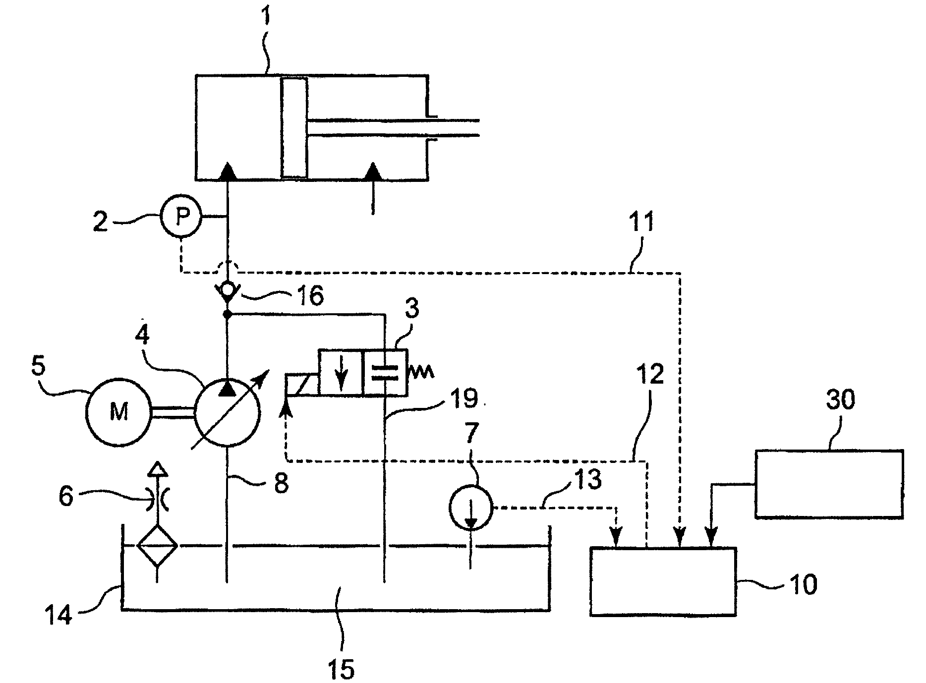
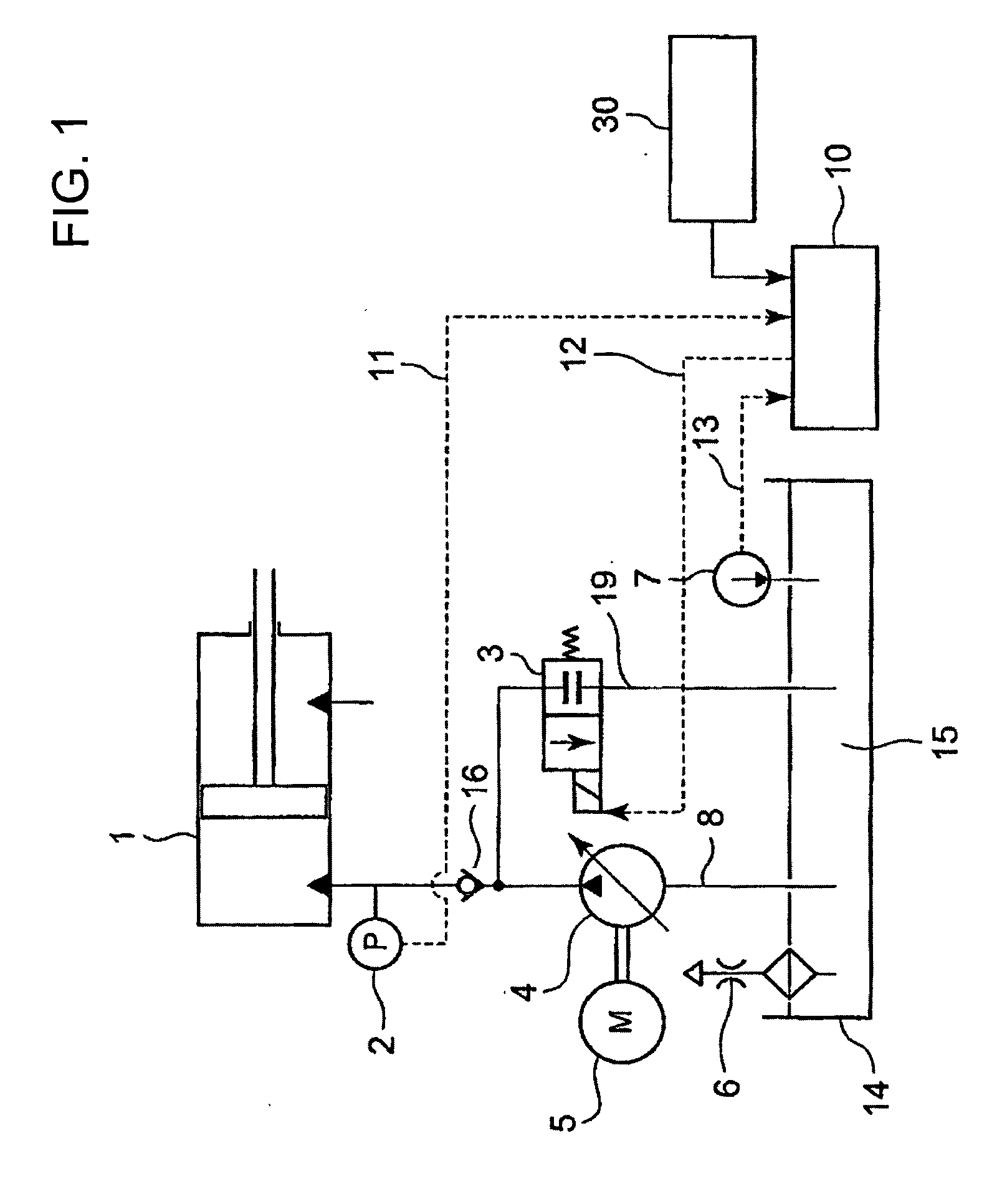
[0033]FIG. 1 is a system diagram of a starter in a hydraulic system for wind turbine blade pitch actuation according to a first embodiment of the present invention.
[0034]In FIG. 1, a hydraulic unit for blade pitch actuation (hydraulic actuation system such as a hydraulic cylinder) designated by reference numeral 1 is supplied with oil 15 stored in a hydraulic tank 14 through a hydraulic main line 8.
[0035]A hydraulic pump 4 to be driven by a motor 5 is placed in the hydraulic main line 8, and the oil 15 in the hydraulic tank 14 is fed by the hydraulic pump 4 into the hydraulic unit 1 through the hydraulic main line 8. A check valve 16 capable of feeding oil only on the side of the hydraulic unit 1 is provided in the hydraulic main line 8 (where a proportional valve, not shown, is provided in the inlet of the check valve 16 to prevent oil from flowing into a cylinder of the hydraulic unit when a bypass valve 3 is turned off). Note that an air breather provided in the hydraulic tank 14...
second embodiment
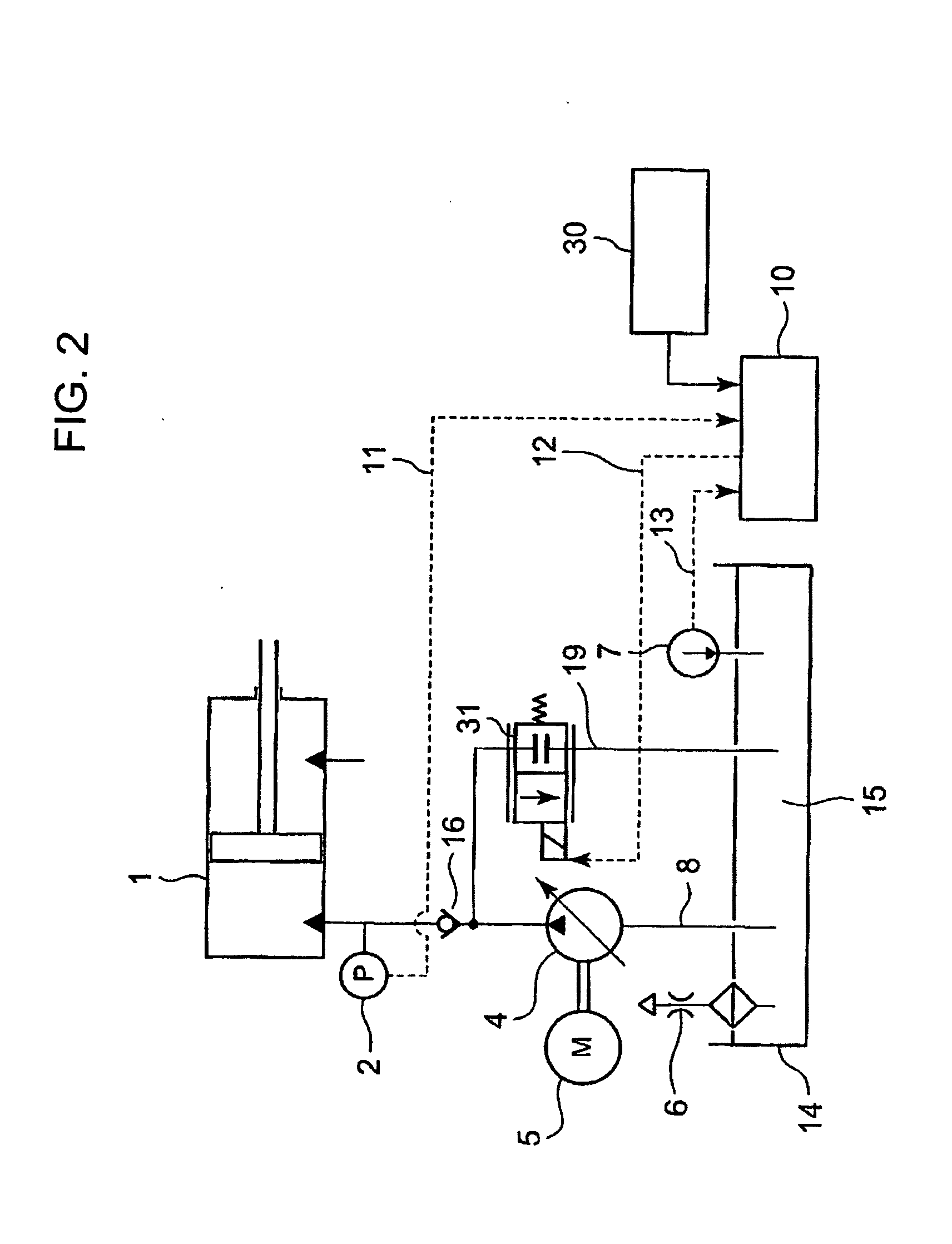
[0056]FIG. 2 is a system diagram of a starter in a hydraulic system for wind turbine blade pitch actuation according to a second embodiment of the present invention.
[0057]This second embodiment differs from the first embodiment in that a variable flow valve 31 is provided in the bypass path 19 to make the flow restriction in the bypass path 19 variable.
[0058]In other words, in a flowchart of FIG. 4 showing the operation of the second embodiment, step (5) is different from that in the first embodiment, and the other steps are the same.
[0059]In step (5), a pressure detection signal from the pressure sensor 2 is received after startup of the hydraulic system to change the amount of flow restriction (throttle) of the variable flow valve 31 in the hydraulic unit 1 in order to control flow path resistance of the bypass path 19.
[0060]Thus, since the flow rate is controlled by the throttle so that it will be located at a point (specified pressure P0) on the preset maximum power generation l...
PUM
 Abstract
Description
Claims
Application Information
 - R&D
- Intellectual Property
- Life Sciences
- Materials
- Tech Scout
- Unparalleled Data Quality
- Higher Quality Content
- 60% Fewer Hallucinations
Browse by: Latest US Patents, China's latest patents, Technical Efficacy Thesaurus, Application Domain, Technology Topic, Popular Technical Reports.
© 2025 PatSnap. All rights reserved.Legal|Privacy policy|Modern Slavery Act Transparency Statement|Sitemap|About US| Contact US: help@patsnap.com


