Clean unit, method of operating clean unit, and connected clean unit

a technology of clean unit and cleaning booth, which is applied in the direction of sterilization of apartments, domestic heating, space heating and ventilation details, etc., can solve the problems of difficult to improve the cleanliness of the conventional clean unit or the clean booth, the gas elements of the installation environment become completely different from the gas elements of the internal environment, and the outside air is not supplied, etc., to achieve the effect of low cost, high flexibility and low cos

Inactive Publication Date: 2010-04-29
CSTEC CORP +1
View PDF2 Cites 24 Cited by
  • Summary
  • Abstract
  • Description
  • Claims
  • Application Information

AI Technical Summary

Benefits of technology

[0068]According to the connected clean unit, a material processing method which enables to carryout process of various kinds of materials easily at low cost with high flexibility corresponding to a total series of process flow for the fields of nanotechnology, biotechnology, plant factory technology, etc., a device manufacturing method which enables to carry out manufacturing process of various kinds of devices using inorganic or organic materials (LSI, light emitting diodes, semiconductor lasers or the like) easily at low cost with high flexibility corresponding to a total series of process flow, a plant cultivation method which enables to carry out plant cultivation process easily at low cost with high flexibility corresponding to a total series of process flow or the like. Also, poultry farming, pig farming, etc. eliminating air infectiveness microbes can be realized, which enables to reduce menace for human society by parasitic zoonosis. In case of SARS outbreak in neighboring area, disposition of cultivating chickens is not required.

Problems solved by technology

However, present situation is far from the above environment level.
However, the conventional clean unit shown in FIG. 1 has a completely closed construction, so that outside air is not supplied.
That is, in the closed circulating system, inside gas elements are consumed or new gas elements occur because of its airtightness so that there occurs another issue that the gas elements of an internal environment become completely different from the gas elements of the installation environment.
On the contrary, it is very difficult to improve cleanliness of the conventional clean unit or clean booth in which an operator can enter, or the conventional clean unit costs a lot of money to improve cleanliness.
Compared to a closed circulating type clean unit, the cleanliness of the conventional clean unit or clean booth is extremely low.

Method used


Image

  • Clean unit, method of operating clean unit, and connected clean unit
  • Clean unit, method of operating clean unit, and connected clean unit
  • Clean unit, method of operating clean unit, and connected clean unit

Examples


first embodiment

[0087]FIG. 2 is a cross-sectional view of a clean unit (clean booth) according to the present invention.

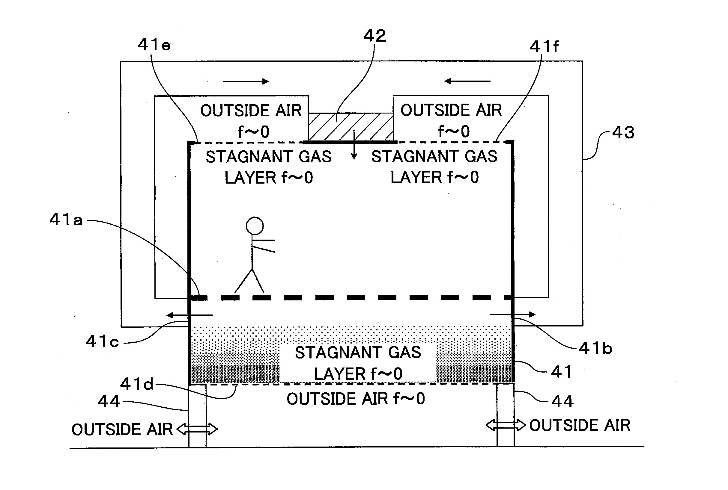
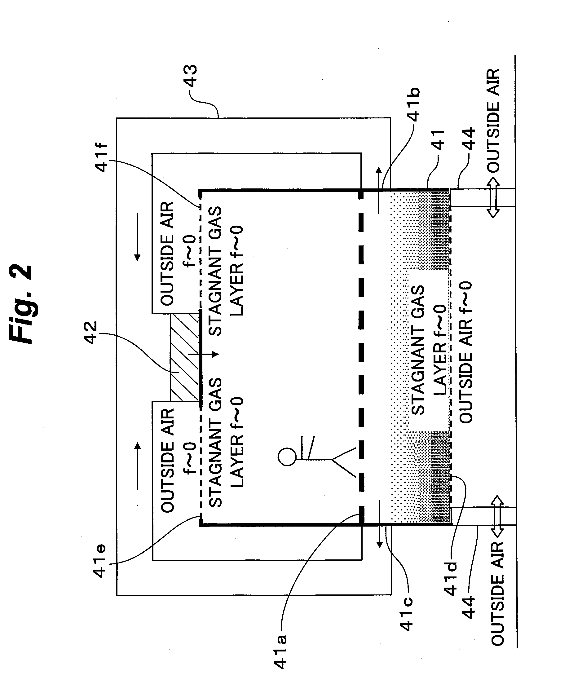
[0088]As shown in FIG. 2, the clean unit has a working chamber 41 with a size in which an operator can enter, and the working chamber 41 has a porous raised floor 41a which permits gas mass flow. The clean unit has a feedback gas flow passage 43 for connecting air-tightly ventilation holes 41b and 41c formed on the wall of the working chamber 41, just under the raised floor 41a and an inlet of a dust filter (a fan filter unit) 42 with a blowing power source provided on top surface (ceiling surface) of the working chamber 41. The raised floor 41a is situated on high position from the base 41d of the working chamber 41. The ventilation holes 41b and 41c which take air into the feedback gas flow passage 43 are located just under the raised floor 41a. Therefore, a stagnant gas layer is formed at the base 41d of the working chamber 41. Accordingly, there is no macroscopic gas flow here...

second embodiment

[0089]FIG. 3 is a cross-sectional view of a clean unit (clean booth) according to the present invention.

[0090]As shown in FIG. 3, the clean unit has the working chamber 41 with a size in which an operator can enter, and the working chamber 41 has a partition wall 45 through which dust particles can not pass (100%) but gas molecules can pass. A homogeneous flow formation board 46 provided on just under the top surface (ceiling surface) of the working chamber 41 is set so that the gas permeability is low just under the dust filter 42 provided at top surface of the working chamber 41, and the opening gradually becomes larger with increasing distance from the dust filter 42 to lateral direction (horizontal direction), and gas permeability increases to make gas flow flowing downward in case viewing from top surface, becomes even. The clean unit has the feedback gas flow passage 43 for connecting air-tightly the ventilation hole 47 formed on the wall of the working chamber 41 and the inle...

third embodiment

[0091]FIG. 4 is a front view of a clean unit according to the present invention, and FIGS. 5A and 5B are a plan view and side elevation of the clean unit.

[0092]As shown in FIGS. 4, 5A and 5B, the clean unit has a hexagonal box shaped working chamber 41. The both sidewalls of the working chamber 41 are parallel each other, and top surface and bottom surface are parallel each other, and both sidewalls and top surface, both sidewalls and bottom surface, both sidewalls and front surface, and both sidewalls and back surface are at right angle each other. The front surface is non-parallel to back surface, and the upper part of top surface is tilted at a predetermined angle in the direction approaching to back surface, for example, 70 to 80 degrees, but the angle is not limited to this. As the front surface of the working chamber 41 is detachable so that the front being detached, necessary apparatus such as a process apparatus and an observation apparatus, etc. can be introduced into the w...


PUM

PropertyMeasurementUnit
depthaaaaaaaaaa
depthaaaaaaaaaa
sizeaaaaaaaaaa

Abstract

In a clean unit which has a dust filter with a blowing power source on the upper surface of a working chamber and which can maintain a clean environment, an external gas flow passage is directly connected or connected through a partition wall, through which dust particles cannot pass but gas molecules can pass, to a feedback gas flow passage for connecting air-tightly a ventilation hole formed in the wall of the working chamber and the inlet of the dust filter to each other. On both sides of the partition wall, the flow velocity vector of a gas flowing in the feedback gas flow passage is made to be equal to the flow velocity vector of the gas flowing in an external gas flow passage.

Description

TECHNICAL FIELD[0001]The present invention generally relates to a clean unit, a method of operating clean unit, and a connected clean unit, which are suitable for application to realize an environment which is capable of maintaining the number of dust particles such as dusts and germs below a predetermined value, or capable of maintaining a clean air environment without these dust particles, and capable of supplying enough oxygen.BACKGROUND ART[0002]A clean room which removes dusts is required for the purpose of attaining high quality and improving yield of precision products for use in the electronics industry, the precision machine industry, and the detailed printing, etc. The International Technology Roadmap for Semiconductor (ITRS) announces that by the development of local cleanization, the requested cleanliness level of a clean room is eased to an environment of normal atmospheric level in 2018. However, present situation is far from the above environment level.[0003]A technol...

Claims


Application Information

Patent Timeline
Patent Type & Authority Applications(United States)
IPC IPC(8): B01L1/04F24F7/06B01D46/00F24F8/108
CPCB01D46/0028B01D46/0091B01D46/10F24F3/161C12M37/00F24F3/1603B01D2279/51F24F3/167F24F8/10F24F8/108
Inventor ISHIBASHI, AKIRA
Owner CSTEC CORP
Why Eureka
Try Eureka