
Heat exchanger with improved condensate removal

a heat exchanger and condensate technology, which is applied in the field of heat exchangers for cooling air, can solve the problems of increasing air side pressure, adverse effects on the overall performance of the refrigerant vapor compression system, and not always draining quickly of condensate on the heat exchange tube and associated fins, etc., and achieves the effect of facilitating condensate drainag

Inactive Publication Date: 2010-05-06
CARRIER CORP
View PDF31 Cites 18 Cited by
  • Summary
  • Abstract
  • Description
  • Claims
  • Application Information

AI Technical Summary

Benefits of technology

[0011]In one embodiment, the heat exchanger includes a plurality of heat exchange tubes arranged in a parallel array and extending longitudinally in a horizontal direction, a plurality of associated generally vertically extending heat transfer fins, and a plurality of airflow guide vanes disposed at the air side inlet to the heat exchange tube and heat transfer fin arrangement for directing the airflow passing into the heat exchange tube array so as to flow more along the condensate accumulating surfaces of each heat transfer fin to enhance drainage of condensate form the heat exchanger external surfaces. The heat exchange tubes may be, for example, of a round, or flat rectangular or flattened oval cross-section. Additionally, at least one partition may be selectively positioned with respect to the heat exchange tube array to locally accelerate the airflow passing therethrough along the heat transfer surfaces of the fins to enhance shedding of condensate therefrom.

Problems solved by technology

However, with many heat exchanger constructions, particularly those having flattened tubes disposed horizontally and extending longitudinally in a horizontal direction, condensate accumulating on the heat exchange tubes and associated fins does not always drain quickly therefrom.
If the condensate accumulating on the external surfaces of the heat exchange tubes and associated fins becomes excessive, overall performance of the refrigerant vapor compression system is adversely impacted.
For example, excessive condensate retention on the external surfaces of the heat exchange tubes can result in increased air side pressure drop through the evaporator, which causes increased fan power consumption, and reduced heat transfer through the heat transfer tubes, which negatively affects evaporator capacity.
Also, since in many air conditioning applications, the indoor air is continuously circulated through the air conditioning system, even when the refrigerant is not circulating through the evaporator heat exchanger, condensate accumulating on the external surfaces of the heat transfer tubes and associated fins of the evaporator may be undesirability recaptured, either through re-evaporation or by re-entrainment, by the air passing through the evaporator.
This recaptured condensate may even be carried back into the conditioned space, which increases the humidity in the conditioned environment, potentiality adversely impacting the comfort of occupants within that conditioned environment.
It should to be noted that cooling heat exchangers of air handling equipment, utilizing cold water or glycol solutions to cool and dehumidify air supplied to the conditioned environment, face an identical problem of condensate blow-off, which causes similar undesired consequences.

Method used


Image

  • Heat exchanger with improved condensate removal
  • Heat exchanger with improved condensate removal
  • Heat exchanger with improved condensate removal

Examples


Embodiment Construction

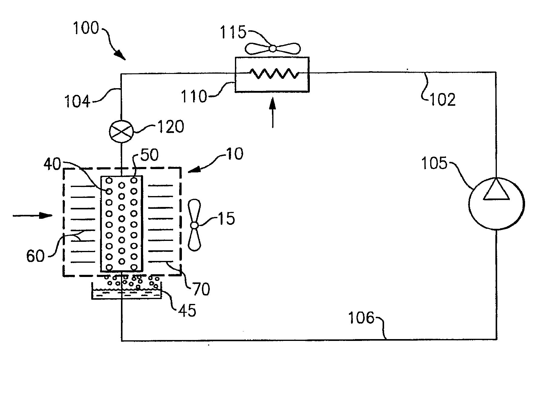
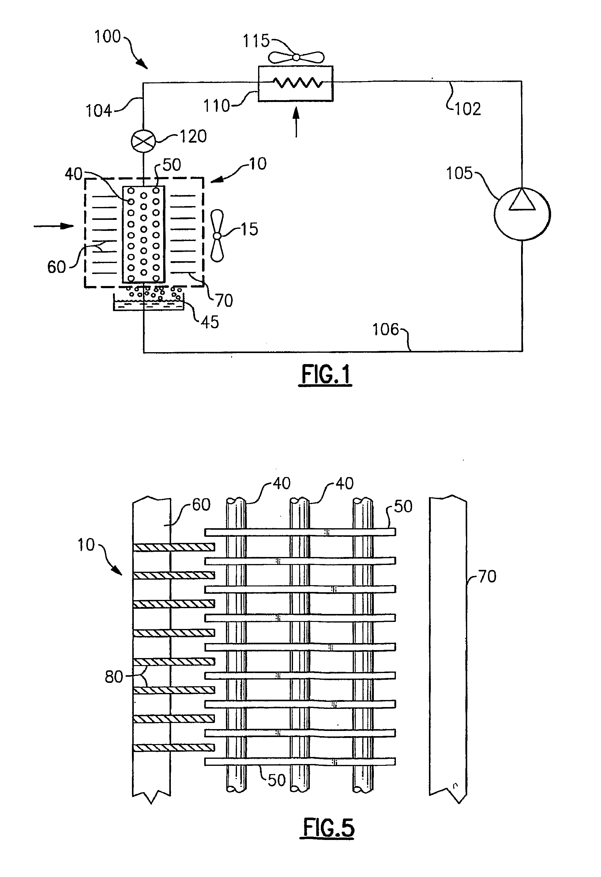
[0021]The heat exchanger of the invention will be described herein in use as an evaporator, in connection with a simplified air conditioning cycle refrigerant vapor compression system 100, as depicted schematically in FIG. 1. Although the exemplary refrigerant vapor compression cycle illustrated in FIG. 1 is a simplified air conditioning cycle, it is to be understood that the heat exchanger of the invention may be employed in refrigerant vapor compression systems of various designs, including, without limitation, heat pump cycles, economized cycles, cycles with tandem components such as compressors and heat exchangers, chiller cycles, cycles with reheat and many other cycles including various options and features. Also, it has to be recognized that although the blow-off phenomenon is described in connection to evaporators of refrigerant systems operating in a vapor compression cycle, cooling heat exchangers of air handling equipment, utilizing cold water or glycol solutions to cool ...


PUM


Abstract

A heat exchanger includes an arrangement of refrigerant conveying heat exchange tubes and associated heat transfer fins and has an airflow inlet and an airflow outlet. A plurality of inlet guide vanes is disposed slightly upstream of the airflow inlet to the heat exchange tube arrangement so as to route incoming airflow through the heat exchange tube arrangement along a desired direction, in relation to the heat exchange tubes and associated fins, so as to improve drainage of accumulated condensate from the external surfaces of the heat exchange tubes and to enhance shedding of condensate from the surfaces of the heat transfer fins. Also, a plurality of outlet guide vanes can be disposed slightly downstream of the airflow outlet from the heat exchange tube arrangement.

Description

FIELD OF THE INVENTION[0001]This invention relates generally to heat exchangers for cooling air and, more particularly, to providing for improved removal of condensate accumulating on the external surfaces of the heat exchange tubes and any heat transfer fins associated with the heat exchange tubes.BACKGROUND OF THE INVENTION[0002]Refrigerant vapor compression systems are well known in the art. Air conditioners and heat pumps employing refrigerant vapor compression cycles are commonly used for cooling or cooling / heating air supplied to a climate controlled comfort zone within a residence, office building, hospital, school, restaurant or other facility. Refrigerant vapor compression systems are also commonly used for cooling air, or other secondary media such as water or glycol solution; to provide a refrigerated environment for food items and beverage products within display cases in supermarkets, convenience stores, groceries, cafeterias, restaurants and other food service establis...

Claims


Application Information

Patent Timeline
Patent Type & Authority Applications(United States)
IPC IPC(8): F25D21/14F25B39/02F24F1/0067
CPCF24F1/0059F24F13/222F25B39/02F25D21/14F28D1/05316F28D1/05383F28F1/32F28F13/06F28F17/005F24F1/0067
Inventor LIFSON, ALEXANDERTARAS, MICHAEL F.
Owner CARRIER CORP
Features
  • Generate Ideas
  • Intellectual Property
  • Life Sciences
  • Materials
  • Tech Scout
  • Unparalleled Data Quality
  • Higher Quality Content
  • 60% Fewer Hallucinations
Learn More