Method for reducing the H2S content of an H2S-containing subterranean formation

Inactive Publication Date: 2010-05-06
BLACK & VEATCH CORP
View PDF2 Cites 5 Cited by
  • Summary
  • Abstract
  • Description
  • Claims
  • Application Information

AI Technical Summary

Benefits of technology

[0010]The invention comprises a method for reducing the hydrogen sulfide content of fluids produced from a hydrogen sulfide-containing subterranean formation, the method comprising: providing a supply of sulfur dio

Problems solved by technology

This gas is considered to be a serious pollutant in crude oil, light hydrocarbon liquids and hydrocarbon gas.
It is also poisonous in

Method used


Image

  • Method for reducing the H2S content of an H2S-containing subterranean formation
  • Method for reducing the H2S content of an H2S-containing subterranean formation
  • Method for reducing the H2S content of an H2S-containing subterranean formation

Examples


Embodiment Construction

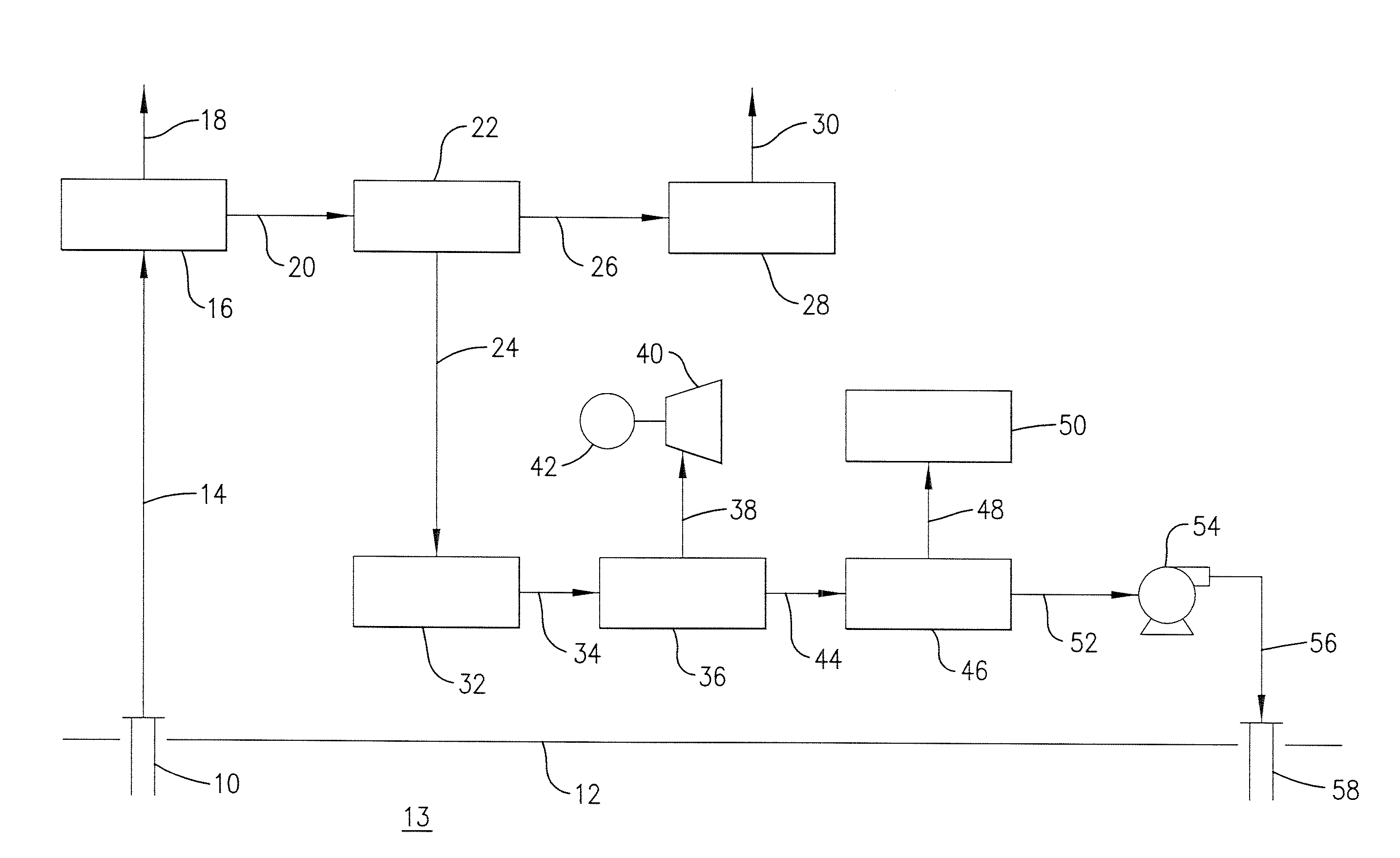
[0017]In the discussion of the Figures, numerous valves, heat exchangers, and the like required to achieve the process flows shown have not been shown in the interest of simplicity since such equipment is well known to those skilled in the art.

[0018]in FIG. 1 a representative process is shown for the production of SO2 for injection into a subterranean formation containing H2S. In the process shown schematically in FIG. 1, a production well 10 is shown extending from an earth surface 12 into a subterranean formation 13 containing H2S and producing gas. Sour gas is recovered through a line 14 and passed to a gas treatment facility 16 where the H2S is removed, along with other materials such as carbon dioxide, condensable gases and the like, as known to those skilled in the art. The sweet gas is then passed through a line 18 as a product to a pipeline or the like. The H2S is recovered through a line 20 and passed to a Claus sulfur recovery unit 22. Such units, as well known to those sk...


PUM


Abstract

A process to reduce the hydrogen sulfide content of a hydrogen sulfide-containing subterranean formation and of products recovered from the subterranean formation by injecting sulfur dioxide into the subterranean formation.

Description

RELATED CASES[0001]This application is entitled to and hereby claims the benefit of the filing date of U.S. provisional application Ser. No. 61 / 198,100 entitled “Method for Reducing the H2S-Containing Subterranean Formation” filed Nov. 3, 2008 by David K. Stevens, Peter D. Clark and Justin J. A. Lamar.FIELD OF THE INVENTION[0002]This invention relates to a method for reducing the hydrogen sulfide content of a hydrogen sulfide-containing subterranean formation and of fluids produced from the subterranean formation.BACKGROUND OF THE INVENTION[0003]In many subterranean formations which contain crude oil, hydrocarbon gases and combinations thereof, the formation may contain substantial quantities of hydrogen sulfide (H2S). This gas is considered to be a serious pollutant in crude oil, light hydrocarbon liquids and hydrocarbon gas. It is also poisonous in certain concentrations. As a result, a continuing effort has been directed to the development of methods whereby the amount of H2S pro...

Claims


Application Information

Patent Timeline
IPC IPC(8): E21B43/22E21B43/16
CPCC09K8/52C09K2208/20E21B43/16
Inventor STEVENS, DAVID K.CLARK, PETER D.LAMAR, JUSTIN A.
Owner BLACK & VEATCH CORP
Why Eureka
Try Eureka