Flash evaporation dealkylation tank for desulfurating pregnant solution

A technology for desulfurization rich liquid and evaporation and dehydrocarbon tank, which is applied in the direction of flash evaporation, liquid separation, gas fuel, etc., which can solve the problems of low conversion rate of sulfur in air distribution, solution foaming and flushing tower, and increase of desulfurization cost, so as to avoid flushing Tower accidents and the effect of reducing desulfurization costs

Inactive Publication Date: 2012-10-17
CHENGDU DEMEI ENG TECH
View PDF4 Cites 3 Cited by
  • Summary
  • Abstract
  • Description
  • Claims
  • Application Information

AI Technical Summary

Problems solved by technology

[0003] When the alcohol amine liquid and the sulfur-containing gas contact the desulfurization absorption tower for desulfurization, a small amount of hydrocarbons will dissolve into the desulfurization rich liquid, and the hydrocarbons will dissolve into the rich liquid, which needs to be removed by flash evaporation before entering the regeneration tower, otherwise it will enter the regeneration system, it will cause the solution to foam and flush the tower, and in severe cases, the device will be shut down. In addition, the hydrocarbons released in the regeneration tower will enter the acid gas, which will bring many difficulties to the subsequent processing of the acid gas.
[0004] In order to remove the hydrocarbons in the desulfurized rich liquid, a flash dehydrogenation tank is usually used for dehydrogenation treatment. At present, the flash dehydrogenation tanks used are divided into vertical tanks and horizontal tanks according to the structure of the tank body. A gas distribution bag for collecting hydrocarbon gas is arranged on the tank, however, there is only one cavity inside the tank body of the existing flash dehydrogenation tank, and the following problems exist in the use of this flash dehydrogenation tank: the flash dehydrogenation tank The flashing temperature of the dehydrogenation tank is generally not too high during flashing, which makes some heavy hydrocarbons with larger molecular weights such as hydrocarbons above C5 and C6 basically unable to flash out, and these heavy hydrocarbons will remain in the storage tank. In the rich solution, after the rich solution enters the regeneration tower, it will cause the regeneration tower solution to foam and flush the tower. In order to avoid the accident of tower flushing in the regeneration tower, defoamers are often added to the alcohol amine solution, which greatly increases the cost of desulfurization, and the rich solution The hydrocarbons in the regeneration tower will enter the acid gas, which will bring many difficulties to the operation of the subsequent sulfur plant, such as carbon deposition, catalyst deactivation, inaccurate air distribution, low sulfur conversion rate, sulfur plugging, etc. In addition, some In order to remove as many hydrocarbons in the rich liquid as possible, the enterprise increases the flash temperature, and the hydrogen sulfide content in the flash hydrocarbon gas is relatively high when flashing at a higher temperature, resulting in the flash hydrocarbon desulfurization If the amount of lean liquid is large, the energy consumption of the system will increase, and even if the flash temperature is increased, it is impossible to remove all the hydrocarbons in the rich liquid. There are some heavy hydrocarbons in the gas. When the gas hydrocarbons containing heavy hydrocarbons enter the gas pipeline network of the factory and are burned as fuel, the heavy hydrocarbons enter the gas system, which will cause the gas to carry liquid, resulting in liquid shock in the pipeline, unstable flames, and insufficient combustion. , black smoke and other phenomena occur

Method used


Image

  • Flash evaporation dealkylation tank for desulfurating pregnant solution

Examples


Embodiment Construction

[0017] The present invention will be further described below in conjunction with the drawings and embodiments.

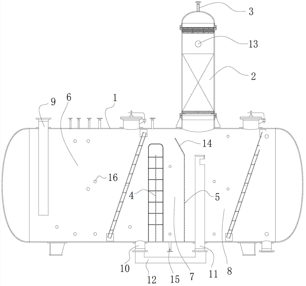
[0018] Such as figure 1 As shown, the flash vaporization and hydrocarbon removal tank for desulfurization rich liquid includes a tank body 1, a gas distribution bag 2 is provided on the top of the tank body 1, and a gas outlet 3 is provided on the gas distribution bag 2, and the tank body 1 A first partition 4 and a second partition 5 are arranged inside. The first partition 4 and the second partition 5 separate the inner cavity of the tank 1 into a rich liquid flash chamber 6, an oil skimming chamber 7, and a hydrocarbon rich liquid A storage cavity 8, the upper part of the rich liquid flash cavity 6 is in communication with the gas distribution bag 2, the upper part of the oil skimming cavity 7 is in communication with the upper part of the de-hydrocarbon rich liquid storage cavity 8, and the rich liquid flash cavity 6 is provided with a rich liquid The inlet 9 and ...


PUM


Abstract

The invention discloses a flash evaporation dealkylation tank for desulfurating pregnant solution, which can thoroughly remove hydrocarbons in pregnant solution. The flash evaporation dealkylation tank comprises a tank body, wherein the top of the tank body is provided with a gas dividing bag, a gas outlet is arranged on the gas dividing bag, the tank body is internally provided with a first clapboard and a second clapboard, the inner cavity of the tank body is divided into a pregnant solution flash evaporation chamber, an oil skimming chamber and a dealkylated pregnant solution storing chamber by the first clapboard and the second clapboard, the upper part of the pregnant solution flash evaporation chamber is communicated with the gas dividing bag, the upper part of the oil skimming chamber is communicated with the upper part of the dealkylated pregnant solution storing chamber, a pregnant solution inlet and a dealkylated pregnant solution outlet are arranged on the pregnant solution flash evaporation chamber, and a dealkylated pregnant solution inlet is arranged on the dealkylated pregnant solution storing chamber. According to the flash evaporation dealkylation tank with the structure, firstly, the light hydrocarbon components in the pregnant solution can be removed by the pregnant solution flash evaporation chamber by means of flash evaporation, and secondly, the heavy hydrocarbon components in the pregnant solution can be removed by the dealkylated pregnant solution storing chamber in a stewing way, so that the hydrocarbons contained in the pregnant solution can be thoroughly removed. The flash evaporation dealkylation tank can be popularized and applied in the field of purifying equipment.

Description

Technical field [0001] The invention relates to the field of petrochemical and natural gas purification equipment, in particular to a flash vaporization hydrocarbon removal tank for desulfurizing rich liquid. Background technique [0002] Refinery gas, natural gas, liquefied petroleum gas, oil field light hydrocarbons, and oil field gas usually contain hydrogen sulfide. Since the further processing, transportation, and use of the above-mentioned materials have strict restrictions on the content of hydrogen sulfide, the Related companies usually need to desulfurize the above-mentioned materials. The desulfurization process currently used is basically the alcohol amine method, that is, the aqueous solution of alcohol amine such as monoethanolamine (MEA) and methyldiethanolamine (MDEA) is used as the desulfurization agent. The solution after the alcohol amine aqueous solution absorbs hydrogen sulfide is called the desulfurization rich liquid. After the heat exchange temperature rise...

Claims


Application Information

Patent Timeline
Patent Type & Authority Applications(China)
IPC IPC(8): B01D3/06B01D17/025C10L3/00C10L3/10B01D53/14
Inventor 郭克雄黄云霞韩洪禄郭毛晓春
Owner CHENGDU DEMEI ENG TECH
Why Eureka
Try Eureka