
Dual Current Switch Detection Circuit with Selective Activation

a detection circuit and switch technology, applied in the field of switch detection circuits, can solve the problems of reducing the voltage rise time, prone to noise, draining the battery, etc., and achieve the effect of reducing the draining of the battery, reducing the current consumption of the battery, and improving the voltage rise tim

Active Publication Date: 2010-05-06
QUALCOMM INC
View PDF9 Cites 7 Cited by
  • Summary
  • Abstract
  • Description
  • Claims
  • Application Information

AI Technical Summary

Benefits of technology

[0009]Particular advantages provided by the one or more of the embodiments of the dual current source switch detection circuit with selective activation are improved voltage rise time and decreased battery drain over conventional resistor-based switches or switch detection circuits. Decreasing battery drain lowers current consumption during a low power mode and improves the overall operating time of the electronic device.

Problems solved by technology

Such resistors increase the drain on the battery, decrease voltage rise time, are susceptible to noise and may produce noise when grounded without parasitic or discrete capacitance.

Method used


Image

  • Dual Current Switch Detection Circuit with Selective Activation
  • Dual Current Switch Detection Circuit with Selective Activation
  • Dual Current Switch Detection Circuit with Selective Activation

Examples


Embodiment Construction

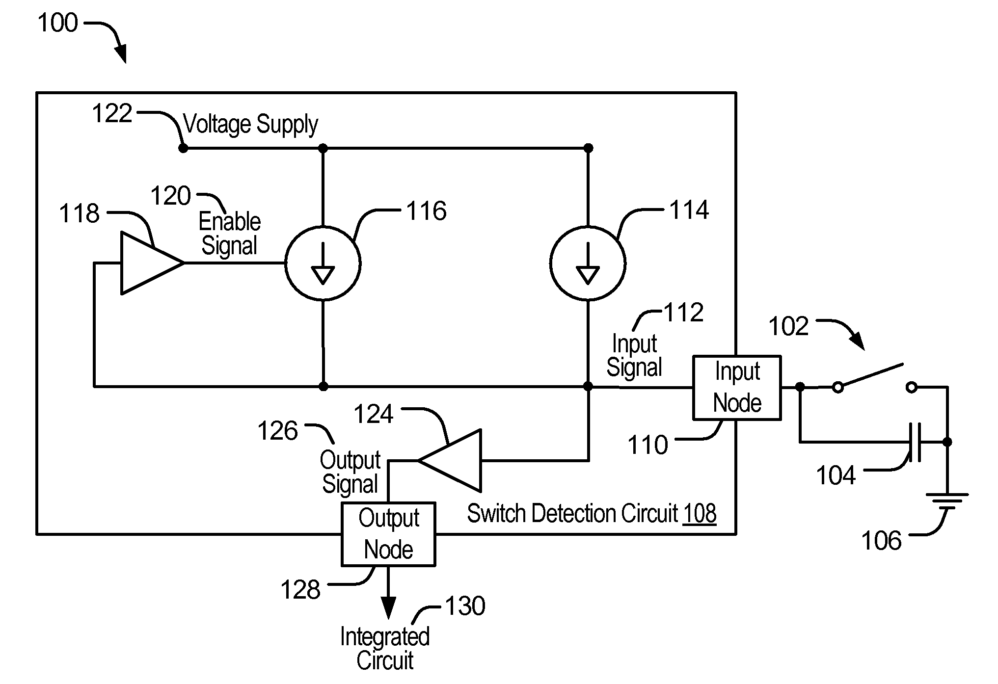
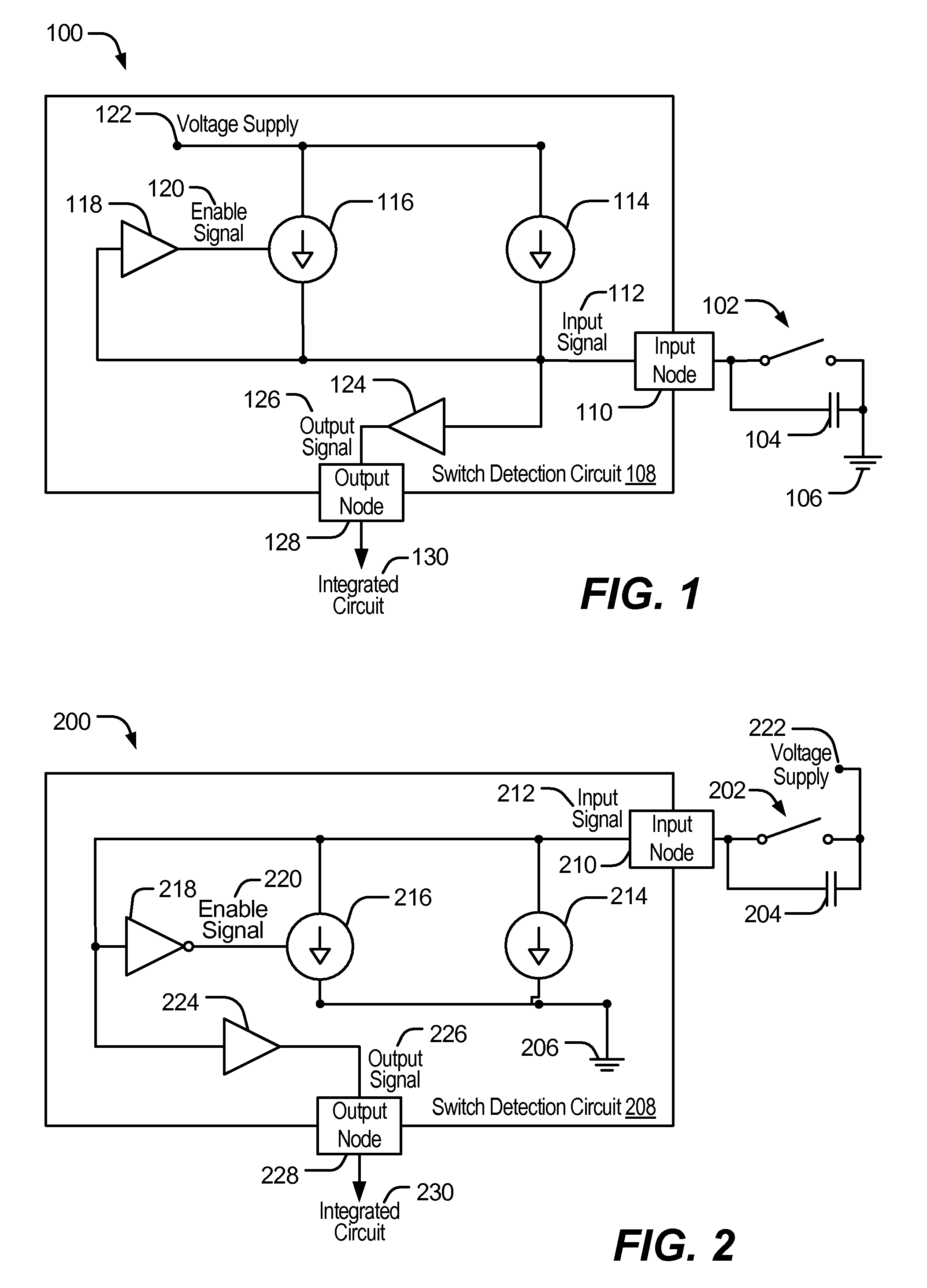
[0022]Referring to FIG. 1, a circuit diagram of a particular illustrative embodiment of a dual current source pull-up switch detection circuit 108 coupled to an external switch 102 is disclosed and generally designated 100. The external switch 102 includes a capacitor 104 to mitigate the external switch 102 from turning on / off multiple times before the contacts of the external switch 102 achieve a good connection. The capacitor 104 may be from about 1 picofarad (pF) to about 15 pF. The capacitor 104 may consist of 1-5 pF of parasitic capacitance or 1-15 pF of discrete capacitance. The external switch 102 is coupled to a ground 106 to provide a grounded signal to the switch detection circuit 108. The external switch 102 may be a mechanical switch (e.g., a carbon switch, a metal contact switch, and similar devices), an electrical switch (e.g., a field effect transistor, bipolar transistor, and similar devices), as well as any other conventional switch or a switch yet to be developed t...


PUM


Abstract

A dual current switch detection circuit with selective activation is disclosed. In a particular embodiment, the switch detection circuit comprises an input node coupled to a switch to receive an input signal from the switch, a first current source coupled to the input node, a second current source coupled to the input node, and a detection circuit having an input coupled to the input node and an output coupled to the second current source to selectively activate the second current source.

Description

FIELD[0001]The present disclosure relates generally to switch detection circuits.DESCRIPTION OF RELATED ART[0002]Advances in technology have resulted in smaller and more powerful computing devices. For example, there currently exist a variety of portable personal computing devices, including wireless computing devices, such as portable wireless telephones, personal digital assistants (PDAs), and paging devices that are small, lightweight, and easily carried by users. More specifically, portable wireless telephones, such as cellular telephones and IP telephones, can communicate voice and data packets over wireless networks. Further, many such wireless telephones include other types of devices that are incorporated therein. For example, a wireless telephone can also include a digital still camera, a digital video camera, a digital recorder, and an audio file player. Also, such wireless telephones can process executable instructions, including software applications, such as a web brows...

Claims


Application Information

Patent Timeline
IPC IPC(8): H02J1/00
CPCH01H9/16H03K19/0016H04M1/0245Y02D70/23Y10T307/858Y10T307/696H04W52/0254Y02D30/70
Inventor GAGNE, JUSTIN JOSEPH ROSEN
Owner QUALCOMM INC
Learn More