

Image pickup apparatus
- Summary
- Abstract
- Description
- Claims
- Application Information
AI Technical Summary
Benefits of technology
Problems solved by technology
Method used
Image

Examples
embodiment 1
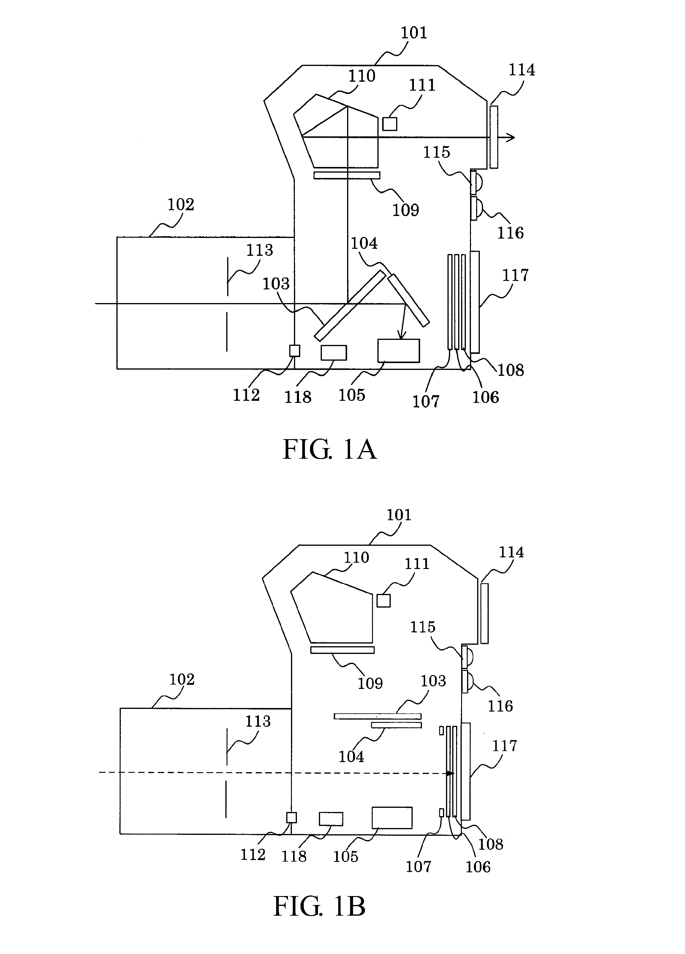
[0028]FIGS. 1A and 1B show a configuration of a single lens reflex digital camera as an image pickup apparatus which is a first embodiment (Embodiment 1) of the present invention. FIG. 1A shows an optical viewfinder mode (second mode) of the camera, and FIG. 1B shows a live-view mode (first mode) and an image pickup operation state for capturing a recording image of the camera.
[0029]In FIGS. 1A and 1B, reference numeral 101 denotes a camera body, to a front face of which an image pickup lens (image pickup optical system) 102 is detachably attached. The camera body 101 and the image pickup lens 102 are electrically connected with each other through mount contacts 112. The image pickup lens 102 includes an aperture stop 113 which enables adjustment of light amount entering the camera body 101.
[0030]Reference numeral 103 denotes a main mirror constituted by a half mirror. In the optical viewfinder mode, the main mirror 103 is obliquely disposed in an optical path (hereinafter, referred...
embodiment 2
[0124]As shown in FIG. 1B, the camera is in the same state (mode) in the live-view mode and during the image pickup operation. Thus, not only during the image pickup operation but also in the live-view mode, the outputs can be read out from the focus detection pixels in the image pickup element 108 and the defocus amount D2 can be also calculated.
[0125]In a second embodiment (Embodiment 2) of the present invention, therefore, after each switching from the optical viewfinder mode to the live-view mode or from the live-view mode to the optical viewfinder mode, defocus amounts D1 and D2 are calculated as defocus amounts before and after the switching. Then, a difference (D1−D2) therebetween is registered in a database to calculate an adjustment value (correction value) A.
[0126]A flowchart of FIG. 11 shows an operation of the camera performed when the adjustment value A is calculated in response to the switching from the optical viewfinder mode to the live-view mode. In Embodiment 2, co...
PUM
 Abstract
Description
Claims
Application Information