Inverter controller

a technology of inverter controller and controller body, which is applied in the direction of process and machine control, pulse technique, instruments, etc., can solve the problems of limiting the decrease, degrading the modulation accuracy, and increasing the noise level

Active Publication Date: 2010-05-06
NEXGEN CONTROL SYST LLC
View PDF3 Cites 25 Cited by
  • Summary
  • Abstract
  • Description
  • Claims
  • Application Information

AI Technical Summary

Benefits of technology

[0017]According to an inverter controller of the present invention, during an operation in the two-phase modulation mode in which switching of any one of three phases configuring the inverter main circuit is dwelled, a carrier

Problems solved by technology

The technique (1) has such problems that when the carrier wave frequency is lowered too far, modulation accuracy is degraded and a noise level becomes greater, and thus t

Method used


Image

  • Inverter controller
  • Inverter controller
  • Inverter controller

Examples


first embodiment

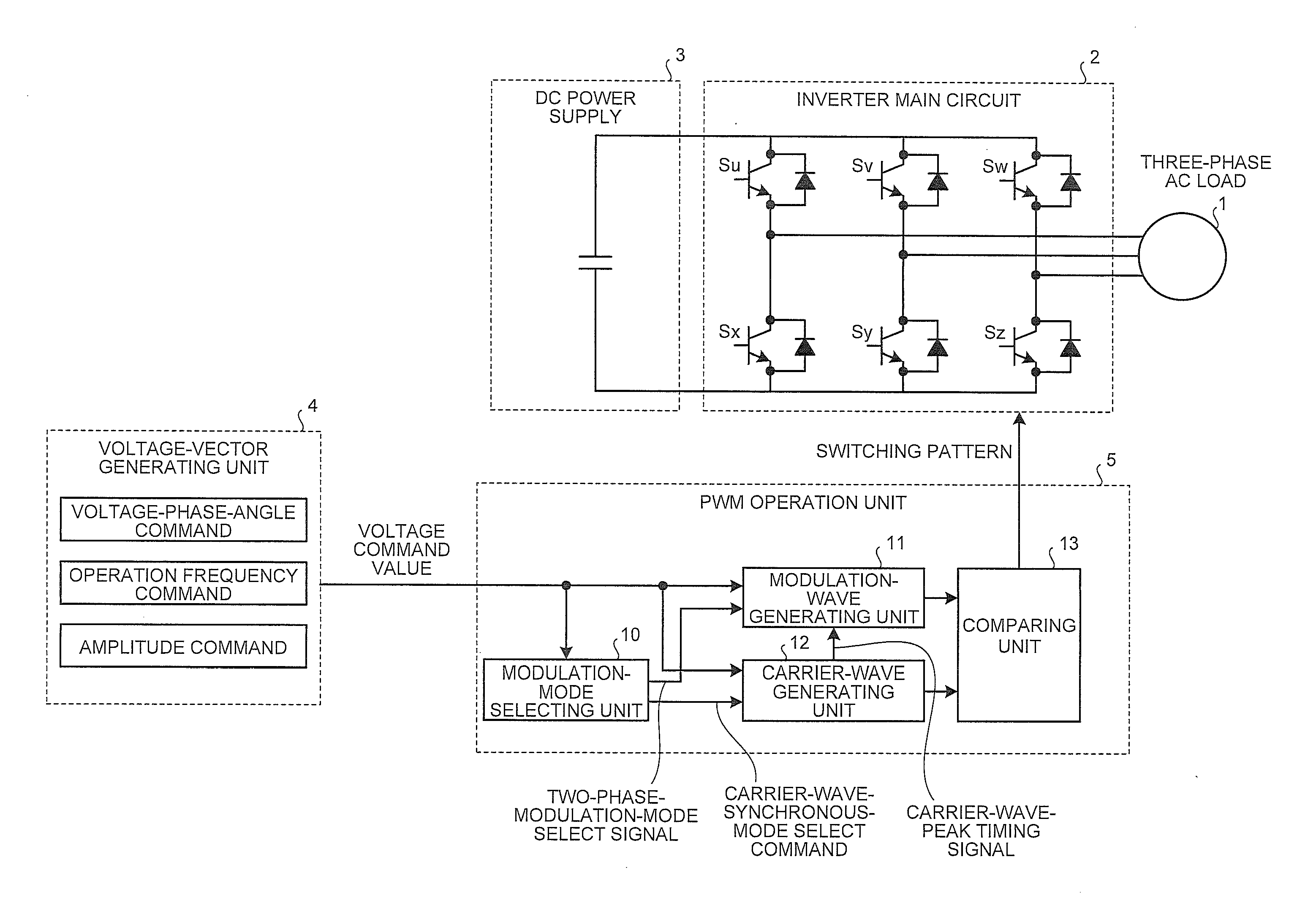
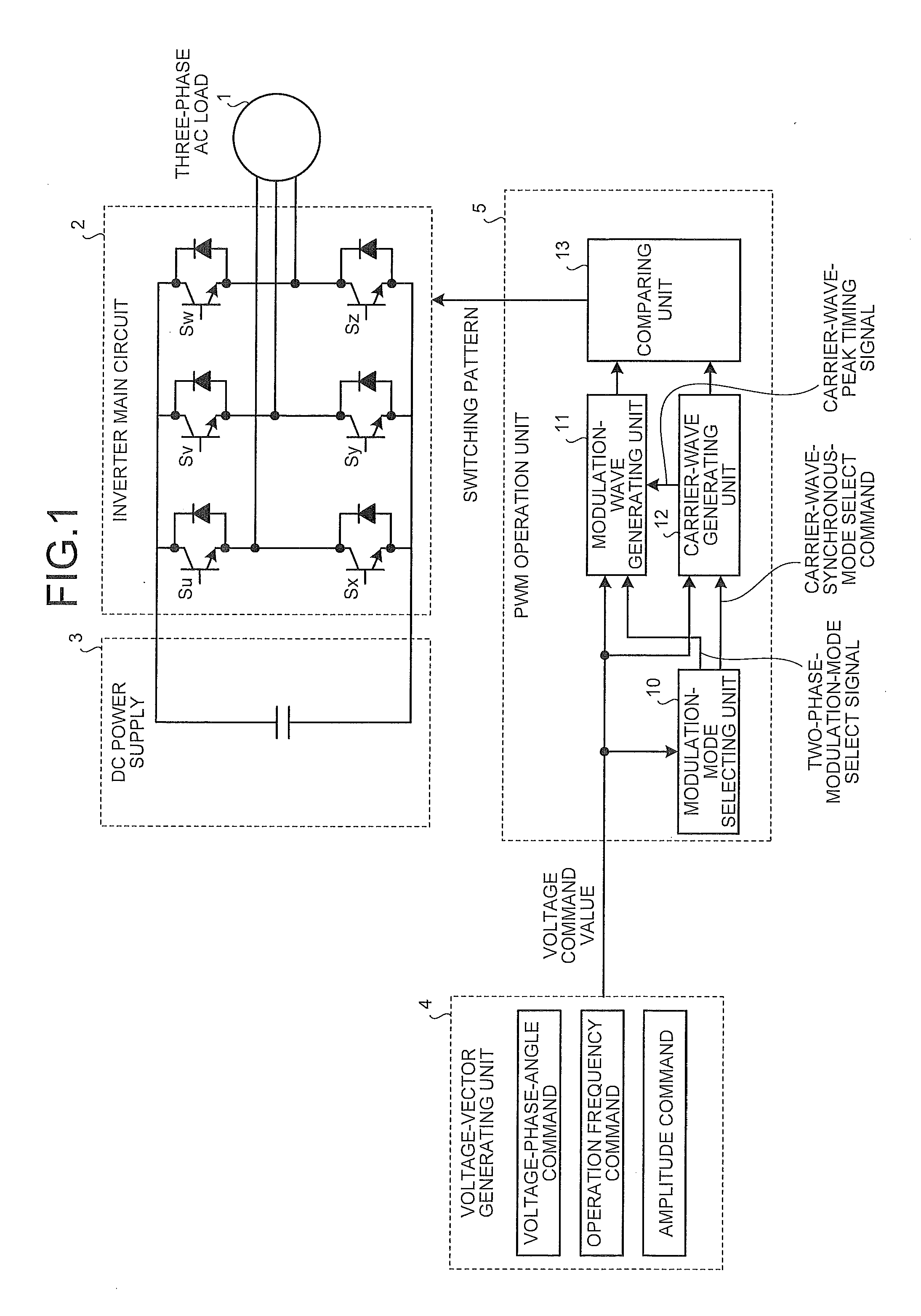
[0057]FIG. 1 depicts a configuration of an inverter controller according to a first embodiment of the present invention, and shows an embodiment of the inverter controller that controls a three-phase AC load 1.

[0058]In FIG. 1, the inverter controller according to the first embodiment includes an inverter main circuit 2, a PWM operation unit 5 that generates a switching pattern used to control the inverter main circuit 2, and a voltage-vector generating unit 4 that generates a voltage command value to the PWM operation unit 5. The inverter main circuit 2 configures a bridge circuit in which juxtaposed pairs of switch units corresponding to three phases are connected, which are formed by connecting in series switch units (Su, Sy, Sw, Sx, Sy, and Sz) each realized by anti-parallel connection of a switching device and a diode, corresponding to two (upper and lower) circuits. A DC terminal of the inverter main circuit 2 is connected to a DC power supply 3 which is a battery or a capacito...

second embodiment

[0101]In the first embodiment, when the modulation wave frequency exceeds the predetermined value, the carrier wave is so set that the carrier wave frequency is an integral multiple of the modulation wave frequency, and thereby, the generation of the modulation phase unbalance or the unnecessary power pulsation is inhibited. On the other hand, when this technique is employed, a changeover of discomfort sounds (mainly, magnetostriction sounds) generated from the inverter main circuit 2 or the three-phase AC load 1 at a changeover timing of the carrier wave frequency occurs, and thus there is a case that this technique is not desired for the use of an inverter in which low noises are regarded as important. In a second embodiment described below, an embodiment suitable for such an inverter in which the low noises are regarded as important is shown.

[0102]FIG. 15 is an example of setting of the carrier wave frequency according to the second embodiment. In FIG. 15, in a region (A) for exa...


PUM


Abstract

To suppress an unbalance of a dwell period in a changeover of phases in which switching is dwelled in an inverter controller. A PWM operation unit 5 includes a modulation-wave generating unit 11 that generates a modulation wave as a voltage command value to an inverter main circuit 2, a carrier-wave generating unit 12 that generates a carrier wave used as a reference for a switching command, and a comparing unit 13 that compares the modulation wave generated by the modulation-wave generating unit 11 and the carrier wave generated by the carrier-wave generating unit 12. During an operation in a two-phase modulation mode in which switching of any one of three phases configuring the inverter main circuit 2 is dwelled, the PWM operation unit 5 controls the carrier-wave generating unit 12 to set a carrier wave frequency to an integral multiple of a modulation wave frequency.

Description

TECHNICAL FIELD[0001]The present invention relates to an inverter controller that controls an inverter driving a three-phase AC system such as an electric motor.BACKGROUND ART[0002]In an inverter main circuit provided in an inverter, which is configured by a bridge-connected semiconductor device unit, a switching loss is generated in the semiconductor device unit due to a switching control by a Pulse Width Modulation (PWM). To prevent the semiconductor device from being breakdown by the heat resulting from the loss, a cooler such as a radiating fin or a fan is arranged in the inverter main circuit. In consideration of downsizing for enhancing the value of an inverter product, downsizing of the cooler is needed. However, to achieve the downsizing, decreasing of the switching loss is first required.[0003]Examples of conventional control techniques for decreasing a switching loss include the following techniques.(1) Decreasing a Carrier Wave Frequency (Switching Frequency)(2) Improving...

Claims


Application Information

Patent Timeline
IPC IPC(8): H02M7/53862
CPCH02M7/53873H02M7/5395H02M2007/53876H02M7/53876
Inventor YAMASAKI, HISANORI
Owner NEXGEN CONTROL SYST LLC
Why Eureka
Try Eureka