Camera body, interchangeable lens unit, and imaging apparatus

Active Publication Date: 2010-05-06
PANASONIC CORP
View PDF5 Cites 32 Cited by
  • Summary
  • Abstract
  • Description
  • Claims
  • Application Information

AI Technical Summary

Benefits of technology

[0012]According to the above aspects, even when an electric contact is repeatedly displaced, a load is not applied to a soldered portion and thus a wire can be prevented from breaking at the soldered portion. In addition, flexibility in the layout of electric contacts can be improved. Furthermore, the electric contacts can be disposed with narrow pitches. Specifically, in the conventional configuration (JP-A-62-27338), since a lead wire is connected to an electric contact, there is limited flexibility in the layout of electric contacts due to the routing of lead wires and the like. However, in the above aspects, since an electric contact is fixed to a substrate through a holding member formed of a conductive material, a problem

Problems solved by technology

However, in the configuration disclosed in JP-A-62-27338, since a lead wire is soldered at a lower end of an electric contact, when the electric contact is repeatedly displaced between the projected position and the retracted position along with the operations of detaching the interchangeable lens unit, a load is applied to a portion where the electric contact and the lead wire are soldered, which highly likely causes a break in the lead wire.
In addition, since the electric contact and an electrical circuit board in the camera body are electrically connected to each other

Method used


Image

  • Camera body, interchangeable lens unit, and imaging apparatus
  • Camera body, interchangeable lens unit, and imaging apparatus
  • Camera body, interchangeable lens unit, and imaging apparatus

Examples


Example

[0031]A camera body and an interchangeable lens unit in the above aspects can take the following aspects based on the above-described configuration. Specifically, in the camera body and the interchangeable lens unit in the above aspects, the configuration may be such that the biasing unit is formed of a conductive material and is held by the holding member, and the body-side contact is electrically connected to the holding member through the biasing unit. By employing such a configuration, an electric contact and a printed circuit board can be electrically connected to each other through a biasing unit.

[0032]In the camera body in the above aspect, the configuration may be such that one end of the biasing unit projects penetrating through the holding member. By employing such a configuration, the material cost required to fabricate the holding member can be reduced.

EMBODIMENT

1. Configuration of an Imaging Apparatus

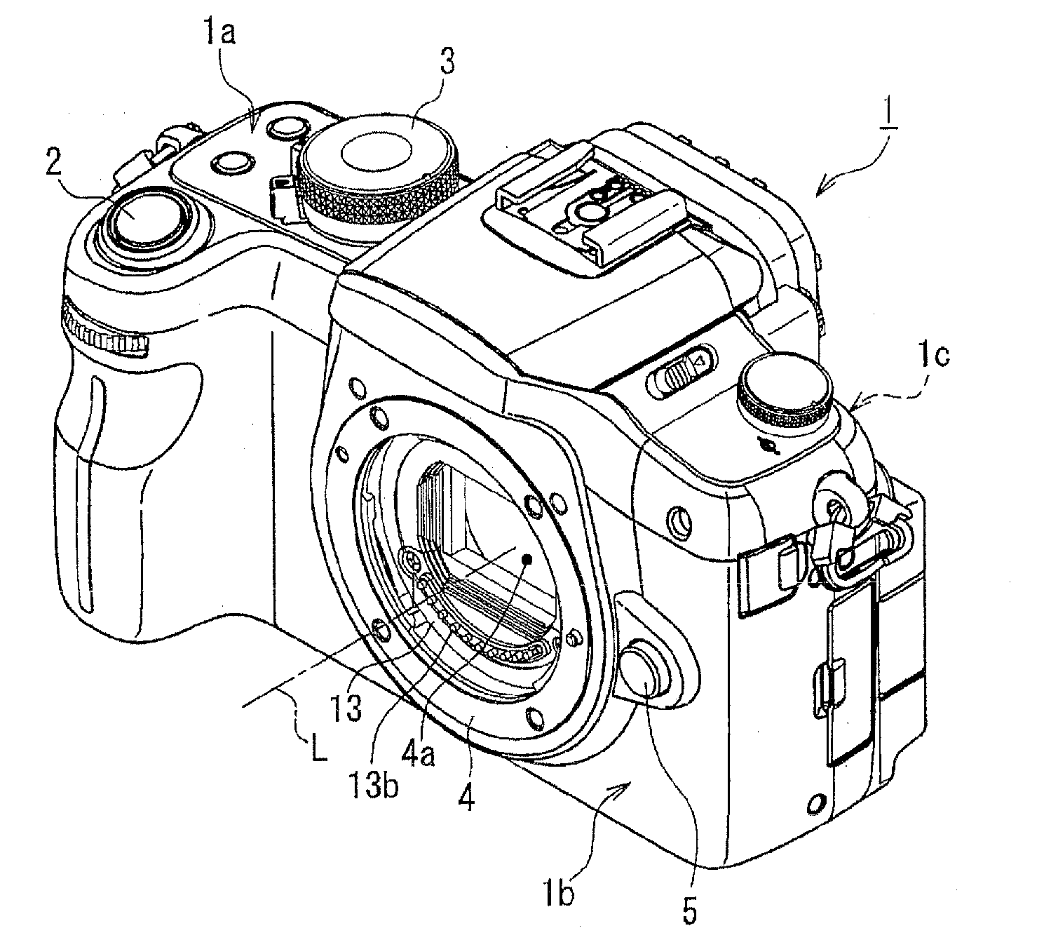
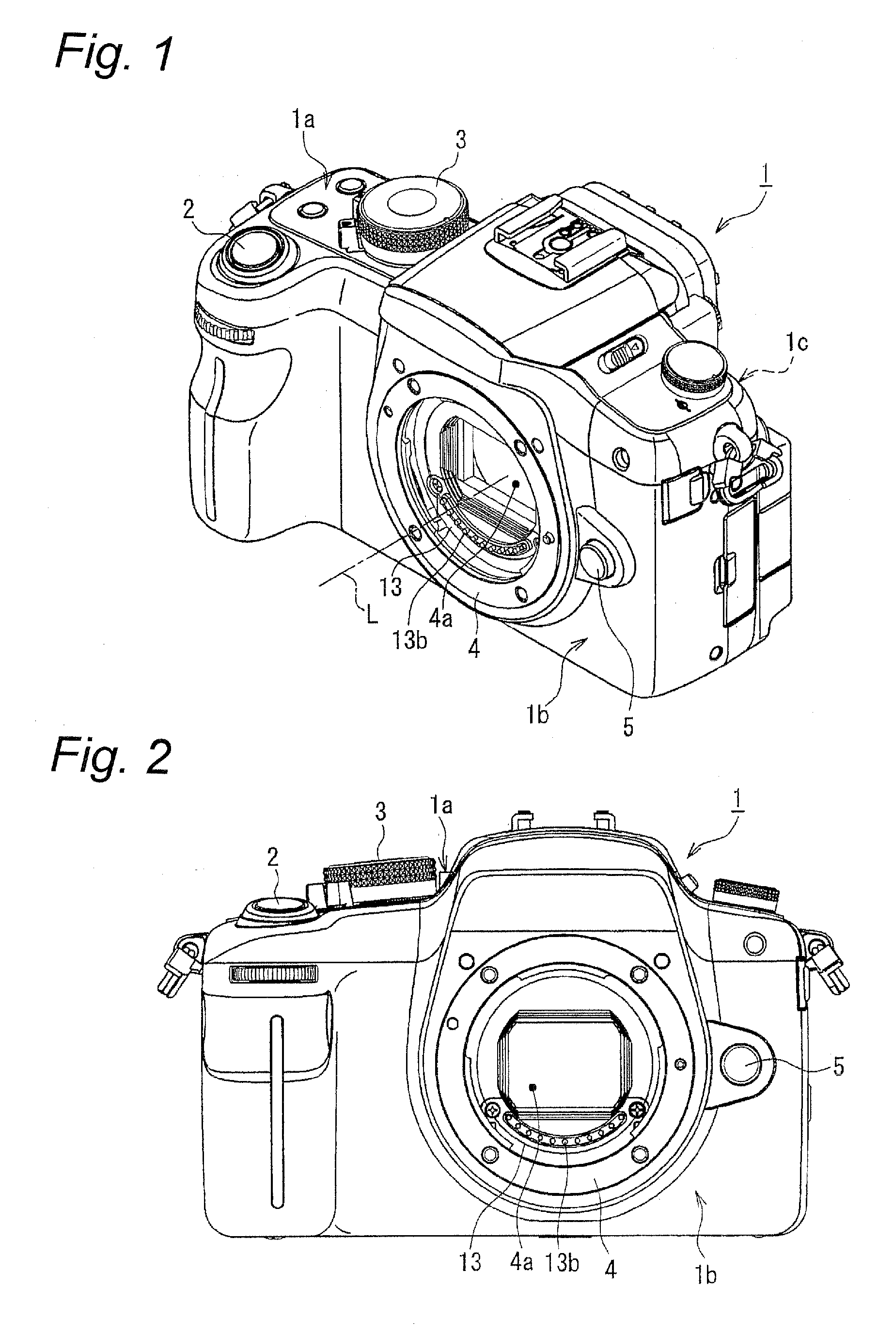
[0033]An imaging apparatus in the above aspect includes a camera body ...


PUM


Abstract

A camera body that includes a lens attaching unit to which an interchangeable lens unit including a lens-side contact is mountable and that communicates information with the interchangeable lens unit when the interchangeable lens unit is attached to the lens attaching unit, the camera body comprising: a substrate; a holding member fixed to the substrate and formed of a conductive material; a body-side contact that is electrically connected to the lens-side contact when the interchangeable lens unit is mounted to the camera body and that is held by the holding member so as to be movable between a projected position at which the body-side contact projects from the holding member and a retracted position; and a biasing unit that biases the body-side contact to the projected position, wherein the body-side contact is electrically connected to the holding member.

Description

BACKGROUND[0001]1. Field of the Invention[0002]The technical field relates to a camera body to which an interchangeable lens unit is mountable, and also relates to an interchangeable lens unit which is mountable to a camera body. Moreover, the technical field relates to an imaging apparatus including a camera body and an interchangeable lens unit which are detachable from each other.[0003]2. Related Art[0004]A single-lens reflex type digital camera generally includes a camera body having an imaging device and the like, and an interchangeable lens unit including lenses and the like. The camera body has a lens mount to which the interchangeable lens unit can be mounted therefrom. In such a digital camera, both the camera body and the interchangeable lens unit have electric contacts so that various information can be communicated between the camera body and the interchangeable lens unit when the interchangeable lens unit is attached to the lens mount of the camera body. Such a configur...

Claims


Application Information

Patent Timeline
IPC IPC(8): G03B17/00
CPCG03B17/00
Inventor YASUDA, KOJI
Owner PANASONIC CORP
Why Eureka
Try Eureka