Turbine rotor blade and fixation structure thereof

a technology of turbine rotor blade and fixing structure, which is applied in the direction of liquid fuel engine, vessel construction, marine propulsion, etc., can solve the problems of affecting the service life of the turbine blade, the forming of the turbine rotor blade takes a considerable amount of time, and the pressure on the steam turbine rotor blade is imposed on the steam turbine rotor blade, etc., to reduce the stress on the blade groove with ease and efficiently support the centrifugal load

Inactive Publication Date: 2010-05-06
HITACHI LTD
View PDF8 Cites 1 Cited by
  • Summary
  • Abstract
  • Description
  • Claims
  • Application Information

AI Technical Summary

Benefits of technology

[0007]An object of the present invention is to provide a turbine rotor blade that is highly manufacturable and capable of reducing the stress caused by centrifugal force.
[0009]The present invention enables the blade groove to efficiently support the centrifugal load on the turbine rotor blade through the blade base portion, thereby making it possible to reduce the stress on the blade groove with ease.

Problems solved by technology

Therefore, the blade base portion may suffer creep damage.
However, as the electric spark forming method or the like is selected for the above-described turbine rotor blade, the forming of the turbine rotor blade takes a considerable amount of time.
Further, steam-induced oscillatory load is imposed on the steam turbine rotor blade.
Therefore, if there is a hole in a platform, bending load on the blade may impose increased stress on the platform.

Method used


Image

  • Turbine rotor blade and fixation structure thereof
  • Turbine rotor blade and fixation structure thereof
  • Turbine rotor blade and fixation structure thereof

Examples


Embodiment Construction

[0015]Embodiments of the present invention will now be described with reference to the accompanying drawings.

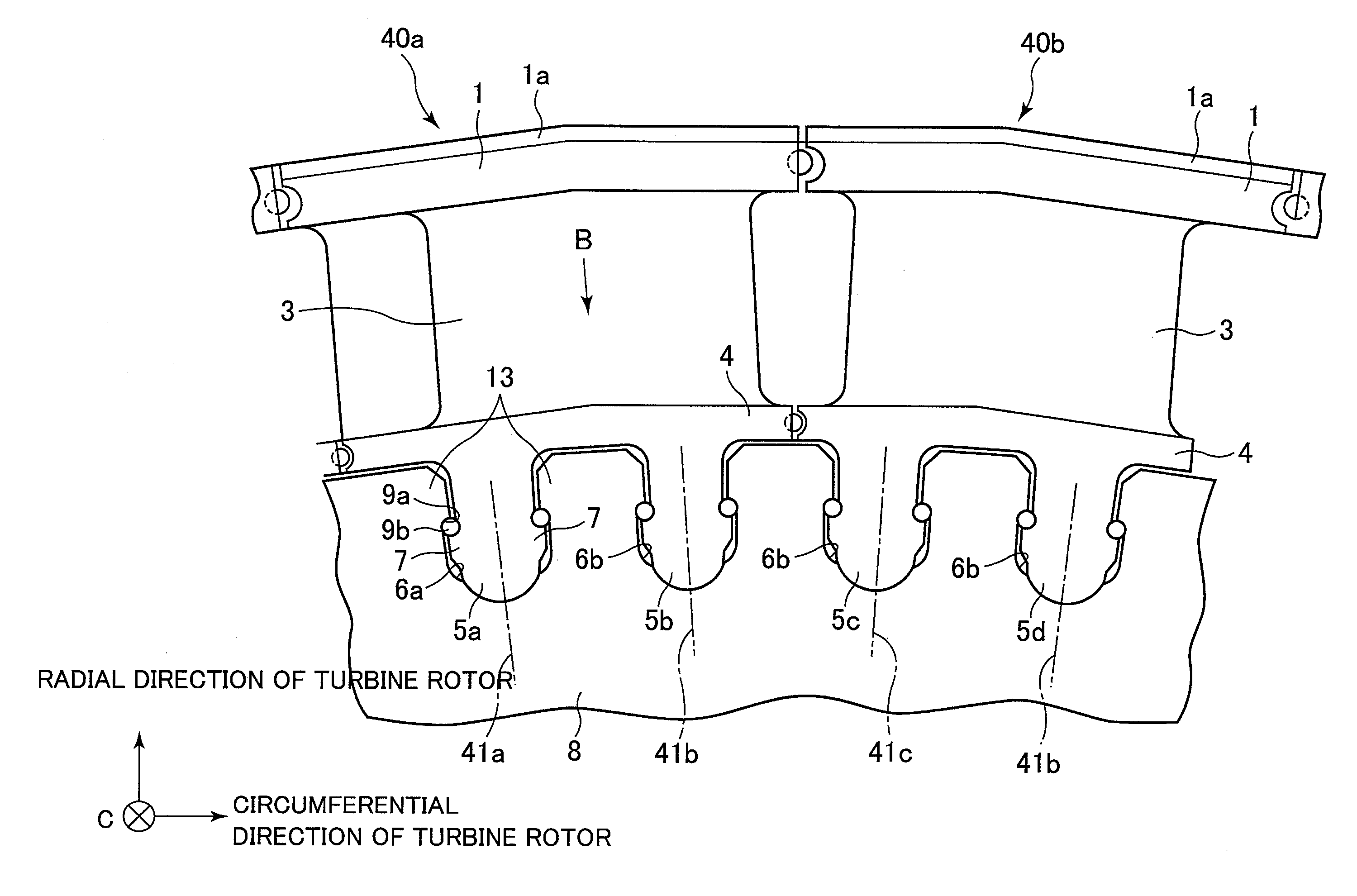
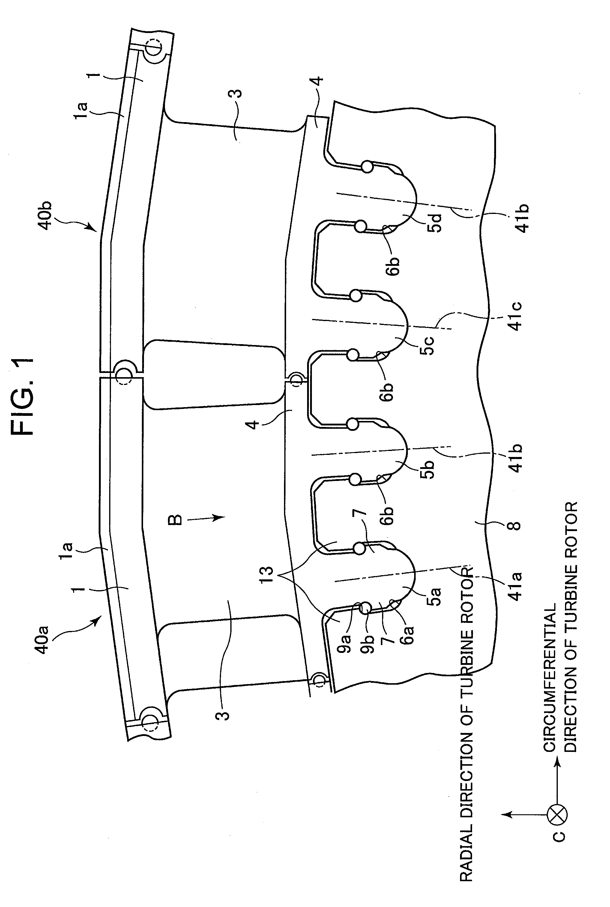
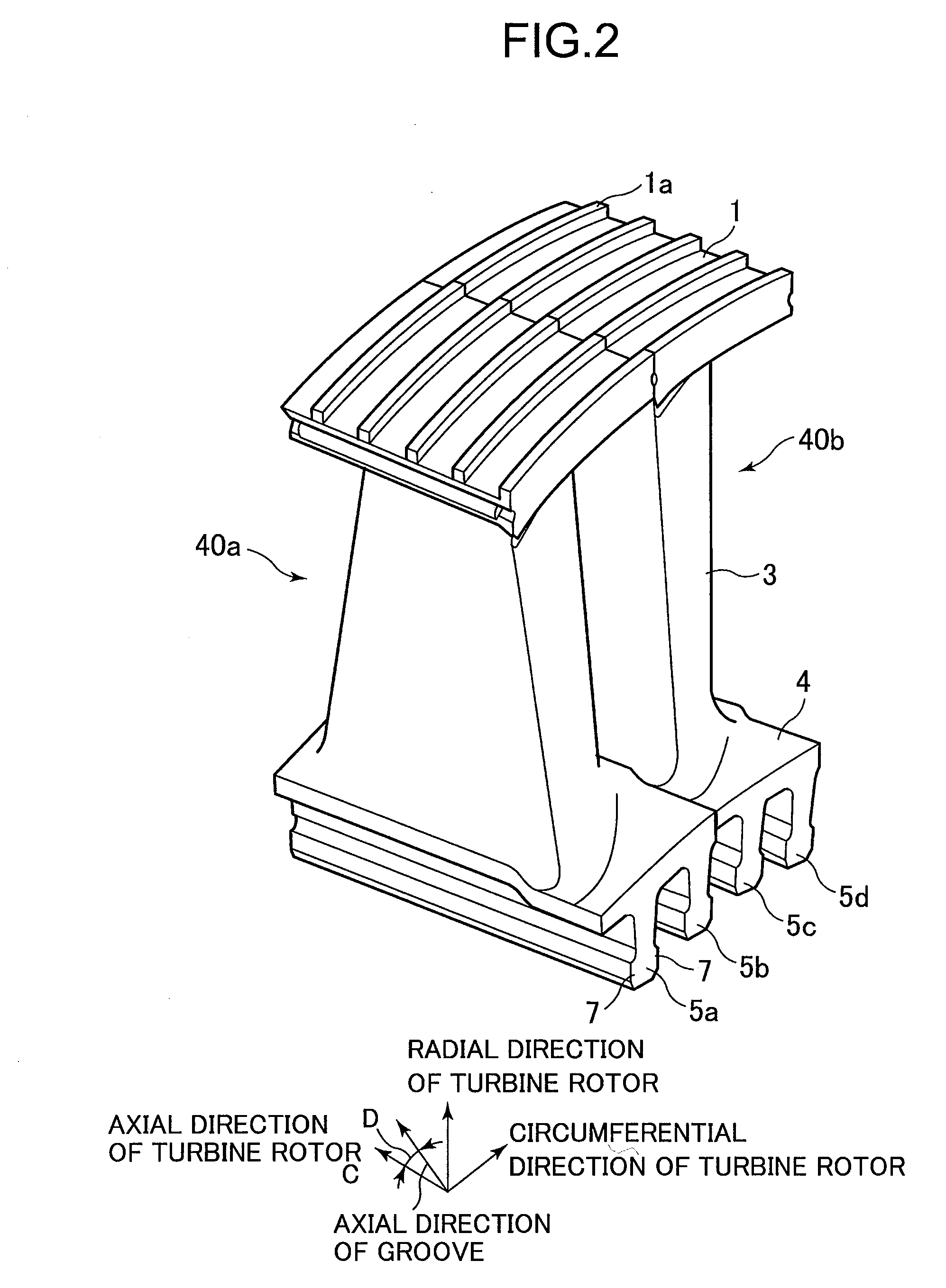
[0016]FIG. 1 is a front view taken in an axial direction of a turbine rotor to illustrate a turbine rotor blade according to an embodiment of the present invention. FIG. 2 is a perspective view of the turbine rotor blade. A radial direction of a turbine rotor, a circumferential direction of a turbine rotor, and an axial direction of a turbine rotor are defined as indicated in these figures.

[0017]Turbine rotor blades 40a and 40b shown in FIGS. 1 and 2 are used with a steam turbine. The turbine rotor blades 40a and 40b each include: a vane portion 3; a shroud 1 which is provided on the leading end of the vane portion 3 (the outer end portion in the radial direction of the turbine rotor); a seal (fin seal) 1a which is provided on the outer circumference of the shroud 1; blade base portion 5 (5a, 5b, and 5c, 5d) which engages with blade groove 6 (6a, 6b, and 6c, 6d) provided on t...


PUM


Abstract

Disclosed is a turbine rotor blade that is highly manufacturable and capable of reducing the stress caused by centrifugal force. The turbine rotor blade includes: a vane portion having a blade leading edge which is positioned upstream in the distribution direction of working fluid, and a blade trailing edge which is positioned downstream of the blade leading edge; and a blade base portion which is extended unidirectionally on a base side of the vane portion and engaged with a blade groove formed in the outer circumference of a turbine rotor. The turbine rotor circumferential position of the end of the blade base portion on the side toward the blade leading edge is different from the turbine rotor circumferential position of the end of the blade base portion on the side toward the blade trailing edge.

Description

BACKGROUND OF THE INVENTION[0001]1. Field of the Invention[0002]The present invention relates to a turbine rotor blade for a turbine such as a steam turbine or a gas turbine. The present invention also relates to a fixation structure of such a turbine rotor blade.[0003]2. Description of the Related Art[0004]A blade base portion (blade implant portion) of a turbine rotor blade for a steam turbine, gas turbine, or the like is variously shaped. The turbine rotor blade is engaged with a blade groove to be mounted on a turbine rotor, the blade groove being complementarily shaped relative to the blade base portion.[0005]At a high- or intermediate-pressure stage in which the turbine rotor blade is exposed to high-temperature steam or gas, high centrifugal force is applied to the turbine rotor blade for a long period of time in a high-temperature atmosphere. Therefore, the blade base portion may suffer creep damage. In view of such circumstances, a technology concerning a steam turbine roto...

Claims


Application Information

Patent Timeline
Patent Type & Authority Applications(United States)
IPC IPC(8): F01D5/30F01D5/14
CPCF01D5/3007F01D5/3053F05D2260/941F05D2250/312F01D5/02F01D5/14F01D5/32
Inventor HAYASAKA, YASUSHITORIYA, HAJIMEMURAKAMI, KATSUHIRO
Owner HITACHI LTD
Why Eureka
Try Eureka