
Torque transmission device for the low vibration transmission of torque via at least one shaft

a transmission device and torque technology, applied in the direction of shafts, springs/dampers, yielding couplings, etc., can solve the problems of audible noise in the passenger compartment of the motor vehicle, and achieve the effect of preventing unresolved buckling in the region of the torque transmission device according to the invention, reducing noise, and increasing resistan

Inactive Publication Date: 2010-05-06
SGF SUDDEUTE GELENKSCHEIBENFAB
View PDF15 Cites 10 Cited by
  • Summary
  • Abstract
  • Description
  • Claims
  • Application Information

AI Technical Summary

Benefits of technology

[0005]By designing the damping arrangement with a stepped progressive characteristic, the effect achieved is that torsional vibrations are reliably damped in a normal operating range of moderate torque transmission. However, if a transmission of very large torques occurs, the characteristic takes a steep course until finally the torque is transmitted directly without further vibration damping.
[0008]A development of the invention provides that a compressible damping layer made of rubber material is provided between the stop formation and the counter stop formation. In order to achieve a specific dynamic behaviour of this damping layer, a development of the invention provides that a thread insert is embedded in the rubber layer, the insert counteracting an excessive deformation. In addition to or as an alternative to this, provision may also be made for a metal insert to be embedded in the rubber layer. Thread insert or metal insert each contribute to the progressivity.
[0011]In the embodiment variant with intermediate element, provision may furthermore be made for the intermediate element to be connected, one behind the other when seen in the axial direction, to the drive element and the driven element, the drive element not overlapping the driven element. A spatially serial arrangement is thus involved here. As an alternative to this, the components drive element, driven element and intermediate element may, however, also overlap in the axial direction in order to save constructional space.
[0015]A further embodiment variant of the invention provides that a rubber-elastic damping layer is provided between the drive element and the driven element and connects the drive element to the driven element, rolling contact bodies being embedded in the damping layer. In this case, provision may be made according to the invention for the rubber-elastic damping layer to provide, in the region of the rolling contact bodies, a play in relation to the respective rolling contact body when seen in the circumferential direction of the torque transmission device. In operation, with this solution, firstly the rubber-elastic damping layer is deformed with relatively little resistance, until the rolling contact bodies come to bear against the boundary surfaces of the rubber-elastic damping layer which define the play. A jump in the characteristic then takes place. Any further deformation can only be achieved under considerably greater resistance, since the rolling contact bodies roll against the boundary surfaces and deform the rubber-elastic damping layer under surface pressure. In this way, too, a stepped progressive characteristic can be achieved.
[0016]In modern vehicle manufacturing, increasing importance is also attached to a controlled behaviour in the event of a crash. In this connection, therefore, it is attempted to design the drive train to be capable of telescoping or collapsing. This means that the drive train can axially shorten as a result of a predetermined axial minimum loading which acts on the drive train in principle only in an accident situation, for example because the engine block is displaced rearwards in the vehicle owing to a head-on collision. In order to assist this, a development of the invention provides that the drive element and the driven element are capable of telescoping in the axial direction with respect to one another when a predetermined axial force is exceeded. As a result, an undesired buckling in the region of the torque transmission device according to the invention can be prevented.

Problems solved by technology

However, with such a direct coupling of the two shafts, vibrations and torsional vibrations which may occur are inadequately damped, leading to audible noises in the passenger compartment of the motor vehicle.

Method used


Image

  • Torque transmission device for the low vibration transmission of torque via at least one shaft
  • Torque transmission device for the low vibration transmission of torque via at least one shaft
  • Torque transmission device for the low vibration transmission of torque via at least one shaft

Examples


Embodiment Construction

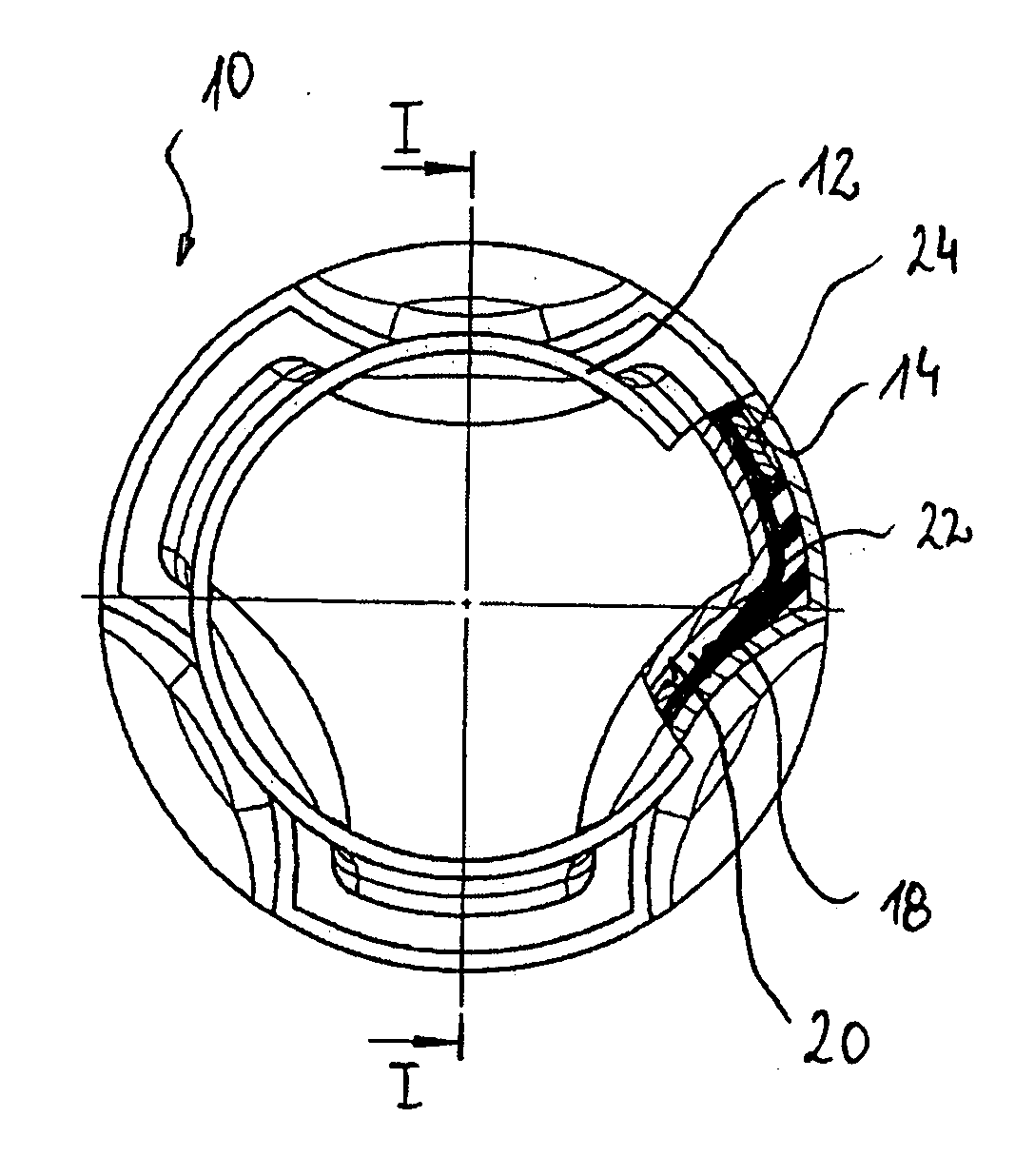
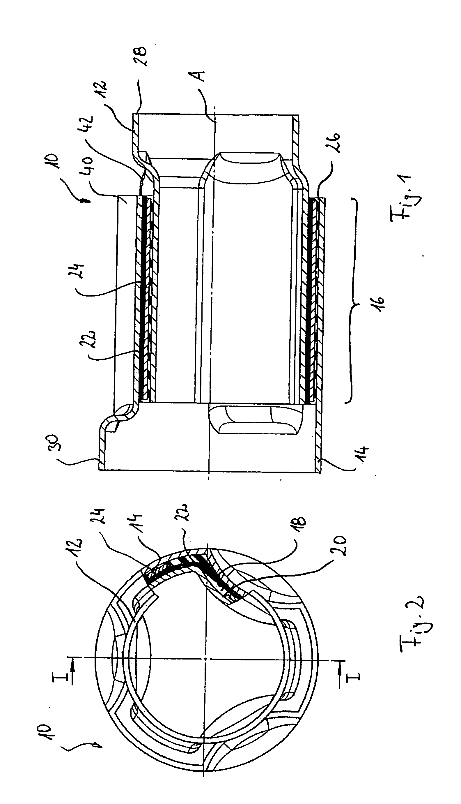
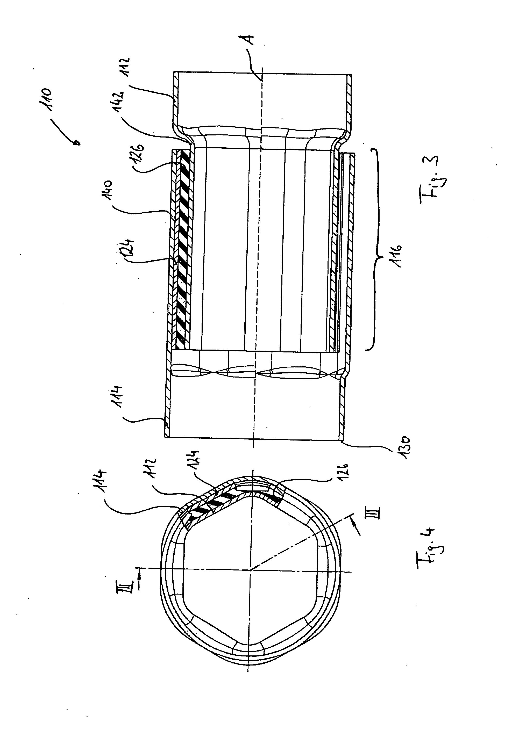
[0037]In FIG. 1 a torque transmission device according to the invention is shown in a longitudinal sectional illustration and is denoted generally by 10. This device comprises a tubular drive element 12 and a driven element 14 connected to the latter. The driven element 14 receives, in its right-hand region, the left-hand region of the drive element 12.

[0038]As can be seen in FIGS. 1 and 2, the drive element 12 and the driven element 14 are designed in a profited manner in their axial overlapping region 16 such that the drive element 12 exhibits stop surfaces 18 and that the driven element 14 exhibits corresponding counter stop surfaces 20. The stop surfaces 18 and counter stop surfaces 20 form a stop formation 40 and a counter stop formation 42 over the entire circumference of the drive element and of the driven element, respectively.

[0039]Between the stop surfaces 18 and the counter stop surfaces 20 there is formed a radial intermediate space, which is filled in the following mann...


PUM


Abstract

Torque transmission device 910 for the vibration-reduced transmission of torques via at least one shaft, having:a drive element 912 and a driven element 914 connected to the drive element 912, there being formed between the drive element 912 and the driven element 914 at least one damping arrangement which connects the drive element 912 to the driven element 914 such that they can rotate relative to one another, the damping arrangement having a stepped progressive characteristic with increasing relative rotation between drive element 912 and driven element 914.

Description

FIELD OF THE INVENTION[0001]The invention relates to a torque transmission device for the vibration-reduced transmission of torques via at least one shaft, having a drive element and a driven element connected to the drive element.BACKGROUND OF THE INVENTION[0002]Torque transmission devices of the above-mentioned type are used, for example, in the drive train of a motor vehicle, such as, for example, between the cardan shaft and the gearbox, the drive shaft and the differential, as well as in the steering-column arrangement. In these devices, a torque is to be transmitted from one shaft to another shaft as far as possible without losses. However, with such a direct coupling of the two shafts, vibrations and torsional vibrations which may occur are inadequately damped, leading to audible noises in the passenger compartment of the motor vehicle. For this reason, torque transmission devices are provided with damping elements which are intended to compensate for such vibrations and tors...

Claims


Application Information

Patent Timeline
Patent Type & Authority Applications(United States)
IPC IPC(8): F16D3/14
CPCF16F15/124F16D3/68F16C3/02F16D3/12
Inventor ROTHE, JOACHIMJERYE, STEFFEN
Owner SGF SUDDEUTE GELENKSCHEIBENFAB
Learn More