

Shockwave valvuloplasty catheter system
a valvuloplasty and shock wave technology, applied in the field of shock wave valvuloplasty catheter system, can solve the problems of narrowing at the opening of the aortic valve, heart murmur, and impairing the blood flow through the valv
- Summary
- Abstract
- Description
- Claims
- Application Information
AI Technical Summary
Benefits of technology
Problems solved by technology
Method used
Image

Examples
Embodiment Construction
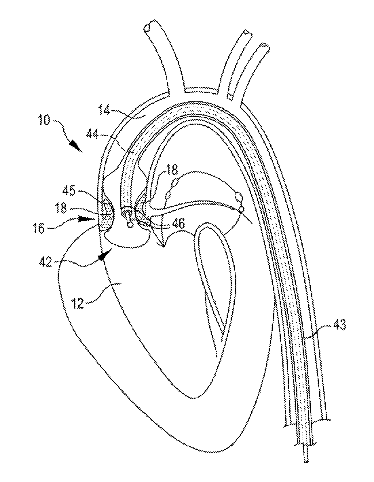
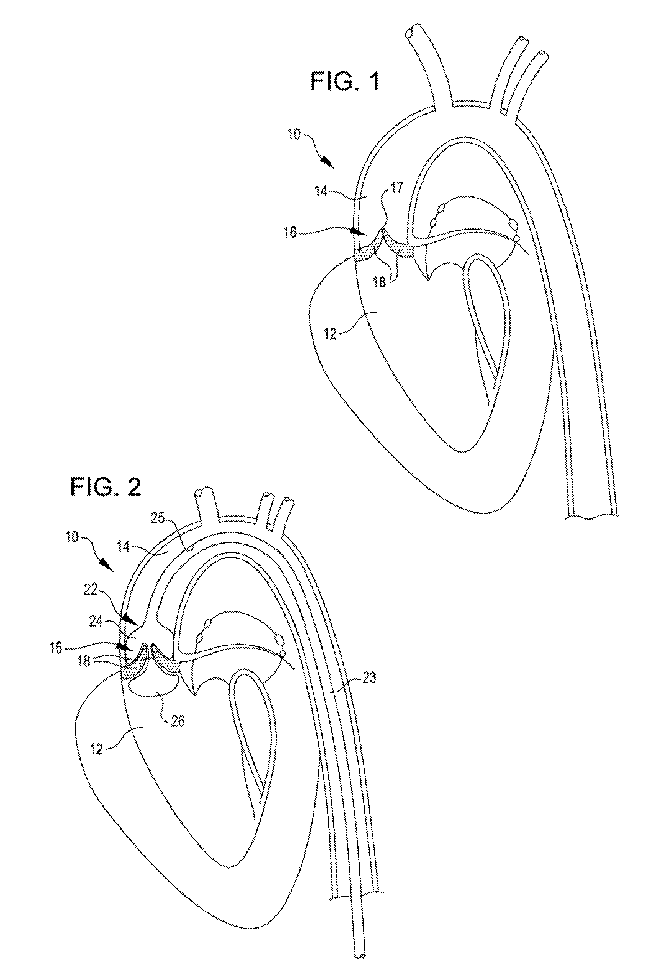
[0026]Referring now to FIG. 1, it is a cut away view of the left ventricle 12, the aorta 14, and the aortic valve 16 of a heart 10 with a stenotic and calcified aortic valve 16. Here more particularly, it may be seen that the opening 17 of the stenotic and calcified aortic valve 16 is restricted in size and that the valve leaflets 18 are thickened with calcium deposits and fibrotic tissue. The thickened leaflets 18 and smaller valve opening 17 restrict blood flow from the heart creating excess work for the heart 10 and poor cardiac output. As previously mentioned, current treatment includes replacement of the valve or attempts too stretch the valve annulus with a balloon.
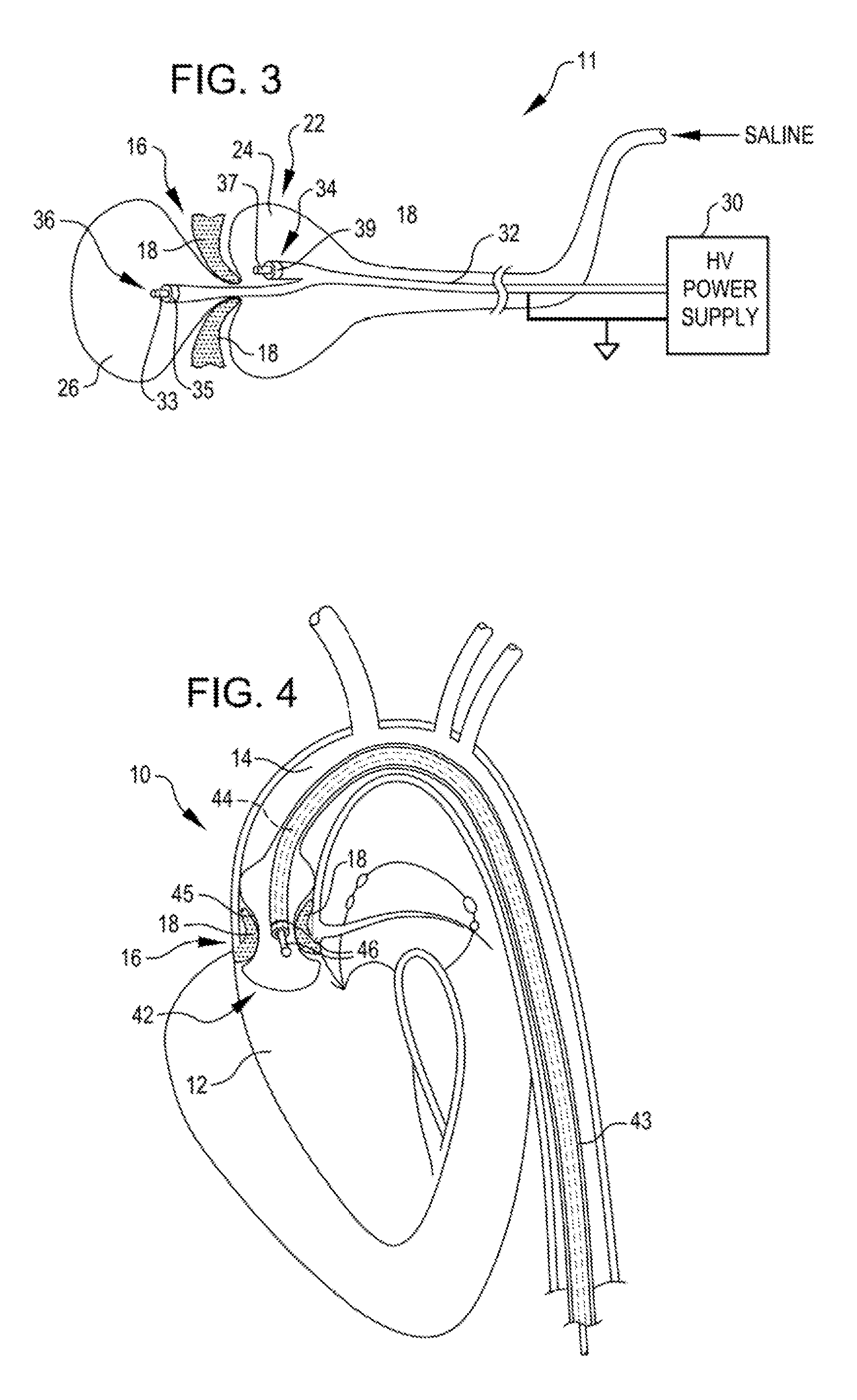
[0027]FIG. 2 is a cut away view of the aortic valve 16 with a treatment balloon 22 placed on both sides of the aortic valve leaflets 18. The balloon 22 may be formed from a compliant or a non-compliant material. The balloon, as seen in FIG. 2, is at the distal end of an elongated tube 23. The treatment balloon 22 ha...
PUM
 Abstract
Description
Claims
Application Information