Introducer for Deploying a Stent Graft in a Curved Lumen and Stent Graft Therefor

a technology of stent graft and lumen, which is applied in the field of introduction for deploying stent graft within a curved lumen, can solve the problems of stent graft not sitting properly in the blood vessel, the lumen diameter of the prosthesis being reduced, and the endovascular techniques for treating these aneurysms are somewhat more difficul

Active Publication Date: 2010-05-06
COOK MEDICAL TECH LLC
View PDF20 Cites 23 Cited by
  • Summary
  • Abstract
  • Description
  • Claims
  • Application Information

AI Technical Summary

Benefits of technology

[0010]The subject matter of the present application seeks to provide an improved introducer and method for deploying a stent graft within a curved lumen, as well as a stent graft for deployment in a curved lumen.

Problems solved by technology

However, when an aneurysm occurs higher up in the aorta, in the region of the descending aorta adjacent the aortic or thoracic arch or in the ascending aorta, endovascular techniques for treating these aneurysms are somewhat more difficult because of the tight curvature of the aortic or thoracic arch, the occurrence of major arteries in the region and the proximity to the heart.
Placement of a substantially cylindrical prosthesis in such a curved region can cause problems.
However, this can result in the stent graft not sitting properly in the blood vessel and in the lumen of the prosthesis being closed off or reduced in lumen diameter.
Furthermore, when deploying a stent graft that is substantially straight in a curved aorta there is a danger that the proximal end of the stent graft, that is, the end nearest the heart, will not lie flat against the walls of the aorta (i.e., the end “face” is not positioned perpendicularly to the wall of the vessel) and blood can flow underneath the edge of the graft, particularly on the inner side of the curve of the aortic or thoracic arch and cause the stent graft to buckle and close off thereby causing serious problems.
Thus, the seal at the proximal end of the stent graft may not be as effective as desired.
This gap can also cause the graft material itself to flap in the fluid flow, leading to unnatural fluid flow and possible premature wear and tear of the stent graft.

Method used


Image

  • Introducer for Deploying a Stent Graft in a Curved Lumen and Stent Graft Therefor
  • Introducer for Deploying a Stent Graft in a Curved Lumen and Stent Graft Therefor
  • Introducer for Deploying a Stent Graft in a Curved Lumen and Stent Graft Therefor

Examples


Embodiment Construction

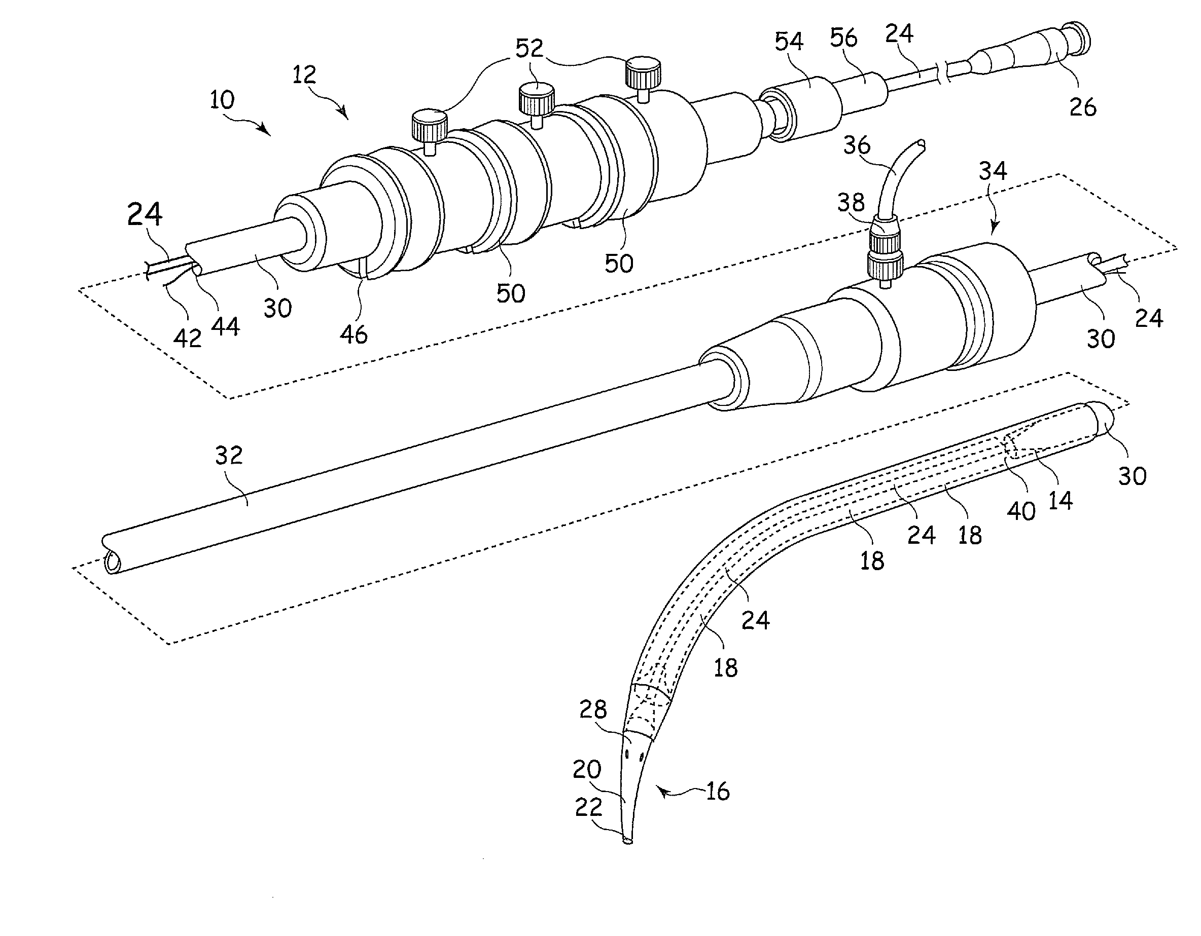
[0045]It is to be understood that the Figures are schematic and do not show the various components to their actual scale. In many instances, the Figures show scaled up components to assist in understanding their structures and functions.

[0046]In this description, when referring to a deployment assembly, the term distal is used to refer to an end of a component which in use is furthest from the surgeon during the medical procedure, including within a patient. The term proximal is used to refer to an end of a component closest to the surgeon and in practise in or adjacent an external manipulation part of the deployment or treatment apparatus.

[0047]On the other hand, when referring to an implantable medical device such as a stent or stent graft, the term proximal refers to a location which in use is closest to the patient's heart, in the case of a vascular implant, and the term distal refers to a location furthest from the patient's heart.

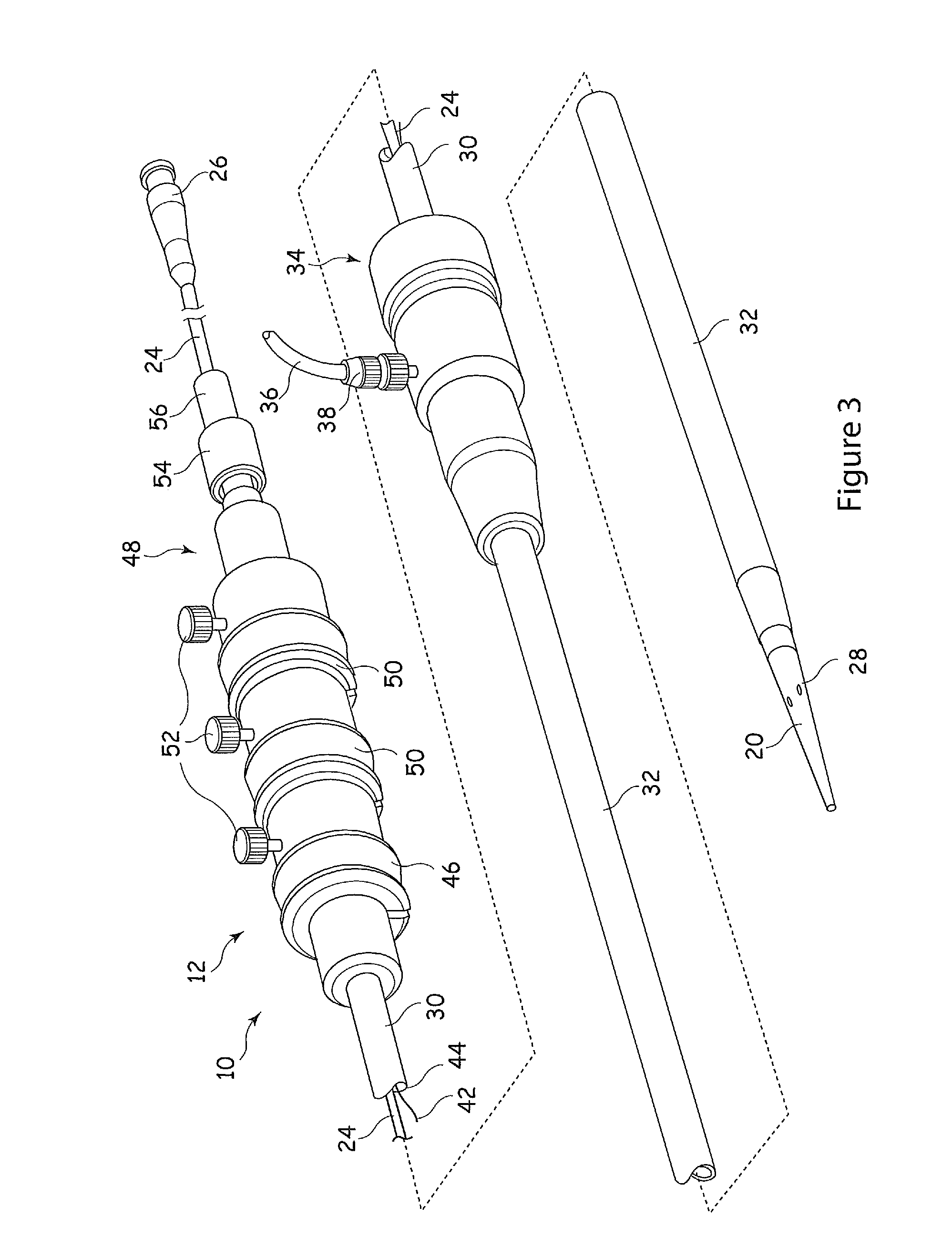
[0048]Referring to FIGS. 3 and 4, an implant de...


PUM


Abstract

A stent graft (18) for deployment in a curved lumen such as the aortic or thoracic arch (130) comprises a constraining mechanism at its proximal end. A stent (4′) provided at the proximal end of the stent graft (18) includes loops of material (11) that co-operate with restraining wires (42) that extend between a central guide wire carrier (24) and a restraining wire cannula (8). The constraining mechanism acts to maintain the proximal stent (4′) constrained at three points around its circumference at both the proximal and distal ends of the proximal stent (4′). The proximal stent (4′) is thus allowed to expand after expansion of the remainder of the stent graft (18) during deployment. In an embodiment, the constraining mechanism acts to constrain two adjacent struts of the proximal stent (4′) at three points radially therearound, at the proximal end of the stent (4′) and at the distal end of the stent (4′). The proximal stent (4′) may then overlap with the interior of an adjacent stent at an inner part (31) of a curved vessel.

Description

CROSS-REFERENCE TO RELATED APPLICATIONS[0001]This application claims priority of United Kingdom patent application number 0820061.0, filed Oct. 31, 2008. This application is related to United Kingdom patent application number 0820066.9, filed Oct. 31, 2008.FIELD OF THE INVENTION[0002]The present application relates to an introducer for deploying a stent graft within a curved lumen. It also relates to a stent graft for deployment within a curved lumen.BACKGROUND OF THE INVENTION[0003]Stent grafts are used to replace or repair vessels of the body such as arteries. A stent graft is usually formed from a tubular body of a biocompatible graft material with one or more stents mounted into or onto the tubular body to provide support therefore. The stents may be balloon expandable stents or self-expanding stents.[0004]Endovascular methods have been proposed for treatment of aneurysms of the aorta particularly where the aneurysm is adjacent the aorta bifurcation. However, when an aneurysm oc...

Claims


Application Information

Patent Timeline
Patent Type & Authority Applications(United States)
IPC IPC(8): A61F2/84A61F2/06A61F2/07A61F2/95
CPCA61F2/07A61F2/95A61F2002/9505A61F2230/0067A61F2002/9517A61F2/89A61F2002/9511A61F2/9517
Inventor KOLBEL, TILORASMUSSEN, ERIK E.OHLENSCHLAEGER, BENTJENSEN, KIM MOEGELVANG
Owner COOK MEDICAL TECH LLC
Why Eureka
Try Eureka