Brake system for a vehicle

a technology for brake systems and vehicles, applied in braking systems, analogue processes for specific applications, instruments, etc., can solve problems such as inoperativeness

Inactive Publication Date: 2010-05-06
ROBERT BOSCH GMBH
View PDF10 Cites 30 Cited by
  • Summary
  • Abstract
  • Description
  • Claims
  • Application Information

AI Technical Summary

Benefits of technology

[0005]The brake system of the invention having the characteristics of independent claim 1 has the advantage over the prior art that during a first mode of operation, preferably a brake-by-wire brake system, the brake booster, controlled by an evaluation and control unit, generates an external force which acts on a piston of the master cylinder, and a first transmission device, which is part of the actuator unit and is controlled by the evaluation and control unit, mechanically uncouples the brake pedal from the piston of the master cylinder as a function of predetermined criteria during the first mode of operation, or couples the brake pedal to the piston of the master cylinder in such a way that the pedal force generated at the brake pedal additionally acts at least partially on the piston of the master cylinder. The brake system of the invention advantageously makes intermediate states between a purely power-brake system and a power-assisted brake system possible. Because it is possible, in the event of a total failure of the brake-by-wire mode of operation or in the event of fading, that is, a loss of friction or of braking torque between the brake lining and brake disk because of high temperature, for an additional amount of brake force to be exerted by the driver to reinforce the brake system, “mixed braking” is possible. Thus if need be, the muscle power of the driver can be used in a purposeful way. Furthermore, by means of a pedal simulator, feedback corresponding to the braking to the driver can be achieved. Compared to a purely brake-by-wire brake system, there is the advantage that the foot power of the driver is employed not only in the event of a complete failure of the brake-by-wire mode of operation, but also in a partial failure of the brake-by-wire mode of operation, which can be caused by a voltage drop, voltage fluctuations, overheating, and so forth, as well as in the event of fading. Moreover, idle travel of the brake pedal that may occur during the bypassing of the pedal simulator can advantageously be avoided.

Problems solved by technology

In a failure of the brake-by-wire mode of operation, the pedal simulator is as a rule bypassed and thus becomes inoperative.

Method used


Image

  • Brake system for a vehicle
  • Brake system for a vehicle
  • Brake system for a vehicle

Examples


Embodiment Construction

[0017]In the drawings, identical reference numerals identify elements and components that perform the same or analogous functions.

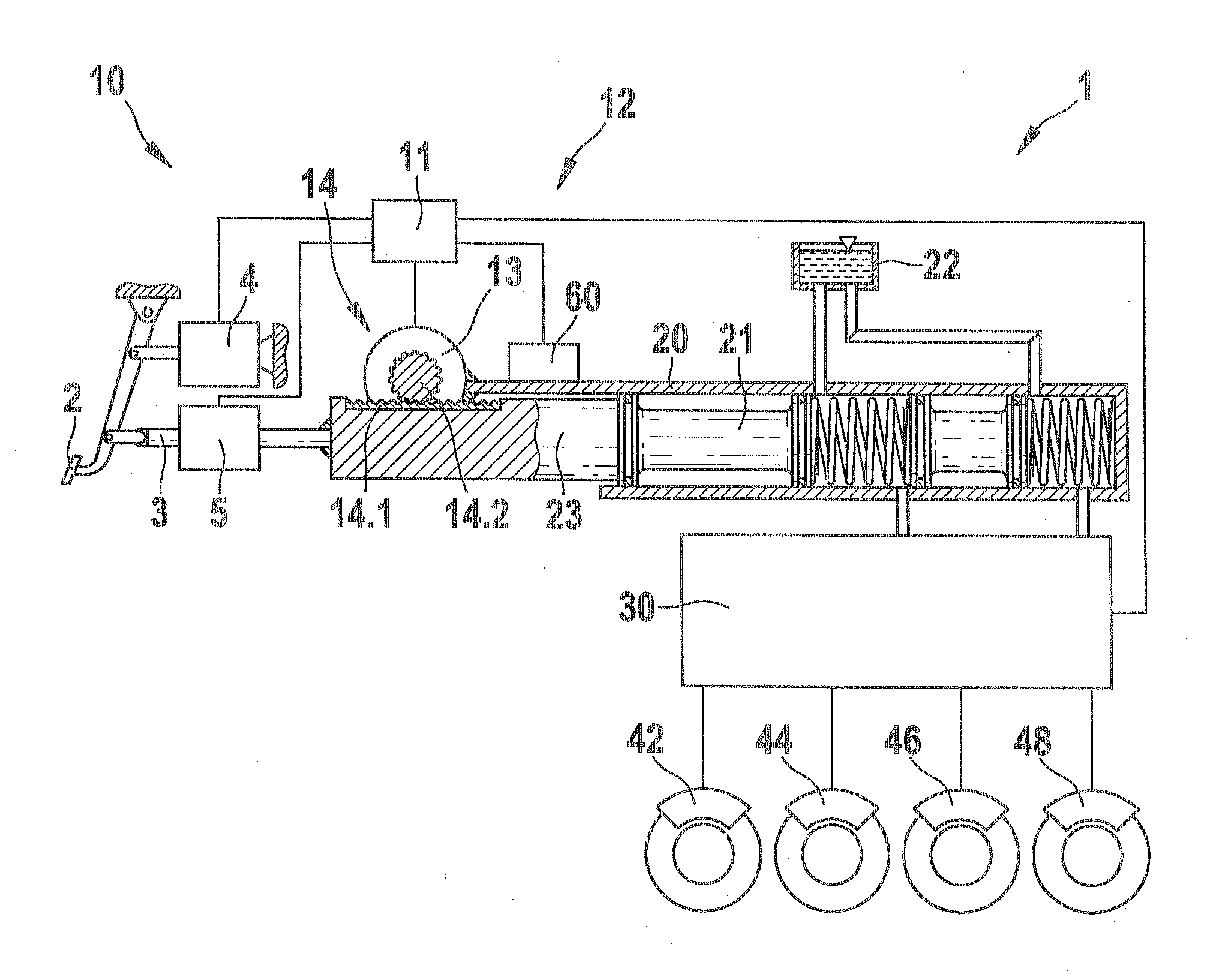
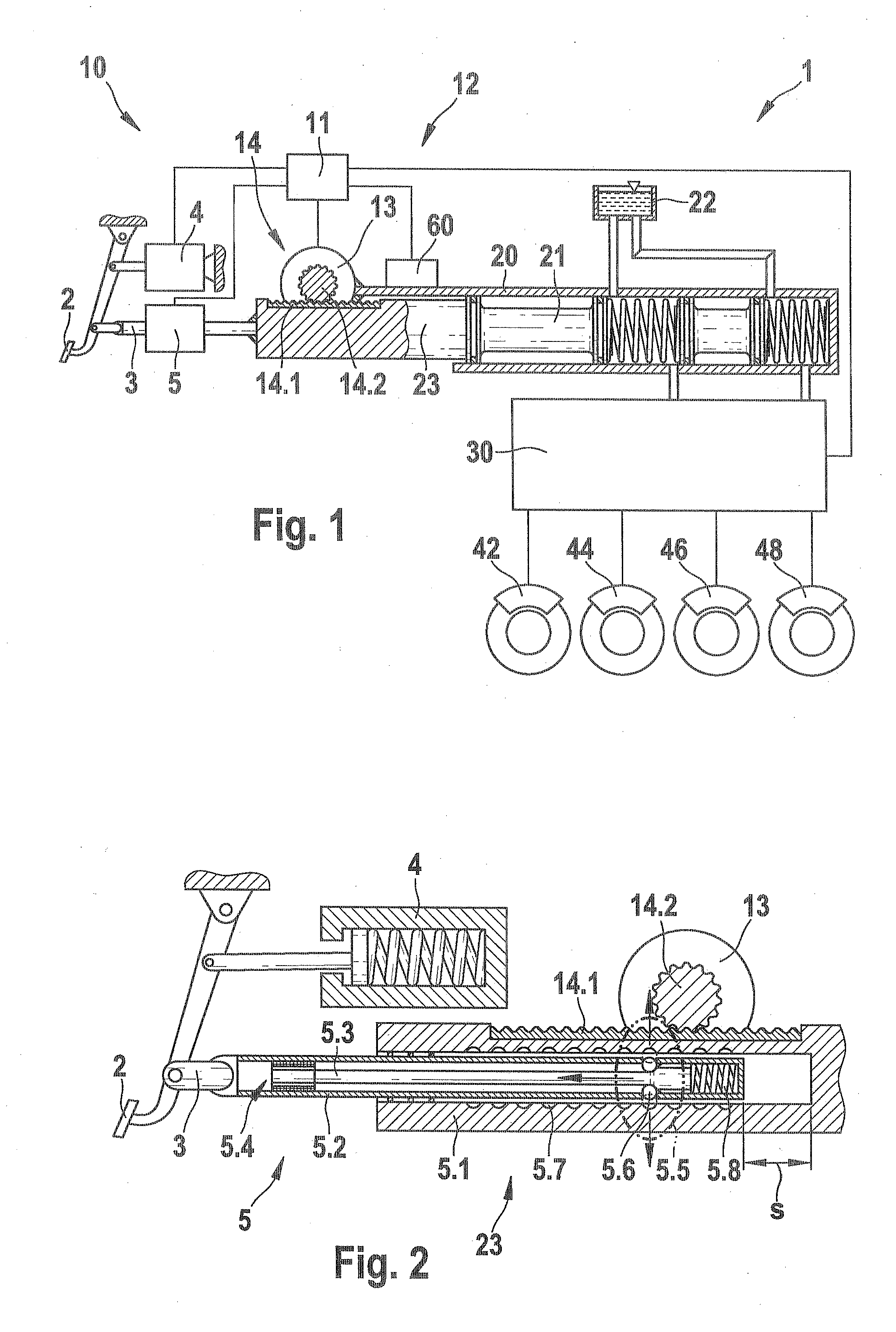
[0018]As can be seen from FIG. 1, a first embodiment of a brake system 1 according to the invention includes an actuator unit 10, which has a brake pedal 2; a pedal simulator 4; a first transmission device, embodied as a locking device 5; and a brake booster, which is embodied here as an electromechanical brake booster12; a master cylinder 20; a fluid control block 30; and a plurality of wheel brakes 42, 44, 46, 48, which are triggered at a predeterminable brake pressure via the master cylinder 20 and the fluid control block 30. The master cylinder 20 is embodied for example as a tandem master cylinder and communicates via suitable fluid connections with a fluid tank 22, which is used as a compensation tank for the brake fluid, and the downstream fluid block 30. The brake pedal 2 is connected to the pedal simulator 4 and to a coupling rod 3 that is embodi...


PUM


Abstract

The invention relates to a braking system (1) comprising an actuator unit (10), said actuator unit comprising a brake pedal (2), a pedal simulator (4), and a brake servo (12), and a main brake cylinder (20) by way of which at least one wheel brake (42, 44, 46, 48) may be actuated, said wheel brake having a braking pressure that may be predetermined, wherein the brake pedal (2) or the brake servo (12) acts on the main brake cylinder (20) to increase or decrease a braking force. According to the invention, during a first operating mode, preferably a brake-by-wire operating mode, the braking force amplifier (12), controlled by an analysis and control unit (11), generates an outside force that acts on a piston (21) of the main brake cylinder (20), wherein the actuator unit (10) comprises a first transmission device (5) that, controlled by the analysis and control unit (11), mechanically decouples the brake pedal (2) from the piston (21) of the main brake cylinder (20) as a function of predetermined criteria during the first operating mode, or couples the brake pedal (2) to the piston (21) of the main brake cylinder (20) such that the pedal force generated at the brake pedal (2) additionally acts at least partially on the piston (21) of the main brake cylinder (20).

Description

PRIOR ART [0001]The invention is based on a brake system for a vehicle as generically defined by the preamble to independent claim 1.[0002]The definition of a brake-by-wire brake system describes a so-called power-brake system, in which, without direct transmission of the muscle power of the driver to the element that generates braking moment, the requisite braking moment is generated with a brake booster. Such brake-by-wire brake systems as a rule have a pedal simulator, which is active during the brake-by-wire mode of operation and simulates a pedal characteristic (force / travel curve), corresponding to the braking event, for the driver. In a failure of the brake-by-wire mode of operation, the pedal simulator is as a rule bypassed and thus becomes inoperative. Brake systems in which the foot power is employed in addition to a boosting force generated by a brake booster are known as auxiliary force brake systems, which are widely used in the passenger car field.[0003]In the Publishe...

Claims


Application Information

Patent Timeline
Patent Type & Authority Applications(United States)
IPC IPC(8): G06F19/00
CPCB60T7/042B60T13/745B60T13/686B60T8/4077
Inventor VERHAGEN, ARMINMAYER, JOCHENNAGEL, WILLI
Owner ROBERT BOSCH GMBH
Why Eureka
Try Eureka