Variable valve gear for internal combustion engine

a technology of internal combustion engine and variable valve gear, which is applied in the direction of machines/engines, output power, couplings, etc., can solve the problems of inability to control, complicated entire structure, and inability to control, so as to avoid prevent interference between the intake valve and the piston, and simple structure and control

Active Publication Date: 2010-05-13
MITSUBISHI MOTORS CORP
View PDF1 Cites 12 Cited by
  • Summary
  • Abstract
  • Description
  • Claims
  • Application Information

AI Technical Summary

Benefits of technology

[0008]The object of the present invention is to provide a variable valve gear for an internal combustion engine provided with a variable valve timing mechanism and a variable valve lift mechanism, in which interference between an intake valve and a piston can be prevented by a simple structure and control.
[0010]Thus, the variable valve lift mechanism changes the lift without substantially changing the valve-opening timing, so that the interference between the piston and the intake valve can be avoided by only setting the most advanced position of the phase by means of the camshaft phase change mechanism. Therefore, the variable valve lift mechanism need not be provided with regulation means, and the variable valve lift mechanism and the camshaft phase change mechanism need not be regulated in cooperation with each other. Thus, in the internal combustion engine furnished with both these mechanisms, interference between the intake valve and the piston can be prevented by a simple structure and control.
[0011]Further, the variable valve lift mechanism can be powered to change the valve-open period even in the most advanced position of the camshaft phase change mechanism, so that the fuel efficiency can be improved.

Problems solved by technology

In one such internal combustion engine provided with both the variable valve lift mechanism and the variable valve timing mechanism, a piston may interfere with the intake or exhaust valve near its top dead center when the lift or the opening and closing timings are considerably changed, if the two mechanisms are only combined.
In the technique described in the above patent document, however, both the variable valve timing and lift mechanisms need to be each provided with the separate regulation means, so that the entire structure is complicated.
Thus, the control is inevitably complicated.

Method used


Image

  • Variable valve gear for internal combustion engine
  • Variable valve gear for internal combustion engine
  • Variable valve gear for internal combustion engine

Examples


Embodiment Construction

[0017]An Embodiment of the present invention will now be described with reference to the accompanying drawings.

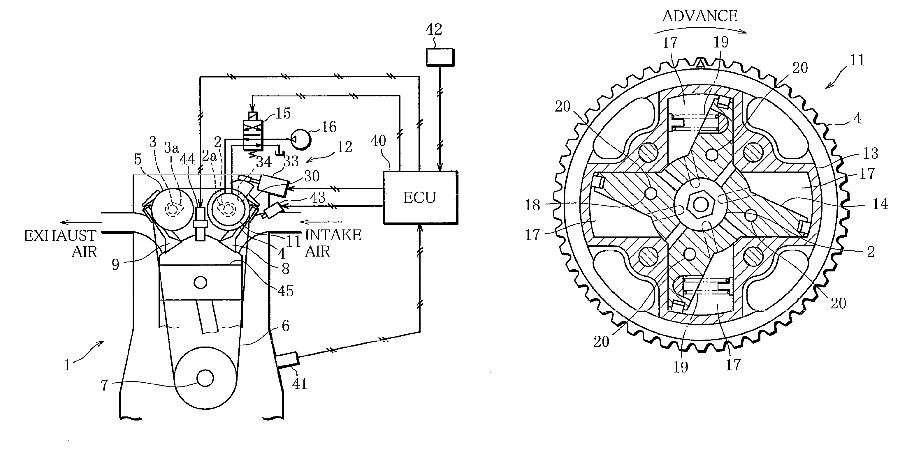
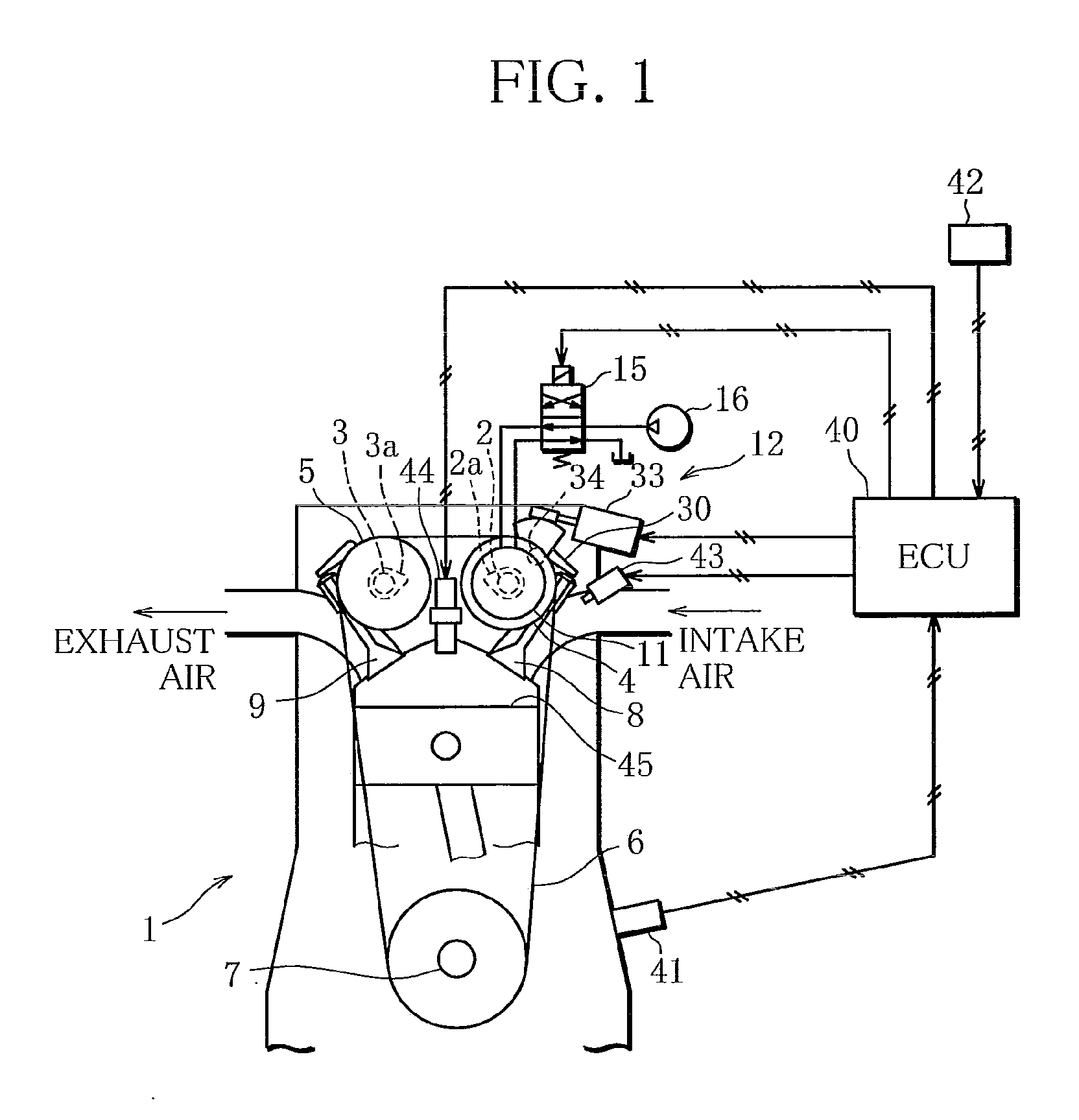
[0018]FIG. 1 is a schematic structure diagram of an internal combustion engine (hereinafter referred to as the engine) 1 provided with a variable valve gear of the present embodiment.

[0019]The engine 1 of the present embodiment includes a DOHC valve train and is mounted as a drive source in a vehicle. Timing pulleys 4 and 5 are connected, respectively, to the respective front ends of an intake camshaft 2 and an exhaust camshaft 3 of the engine 1. The pulleys 4 and 5 are coupled to a crankshaft 7 by a timing belt 6. As the crankshaft 7 rotates, the intake and exhaust camshafts 2 and 3 are rotated together with the pulleys 4 and 5. An intake valve 8 is opened and closed by driving an intake cam 2a on the intake camshaft 2, and an exhaust valve 9 by an exhaust cam 3a on the exhaust camshaft 3.

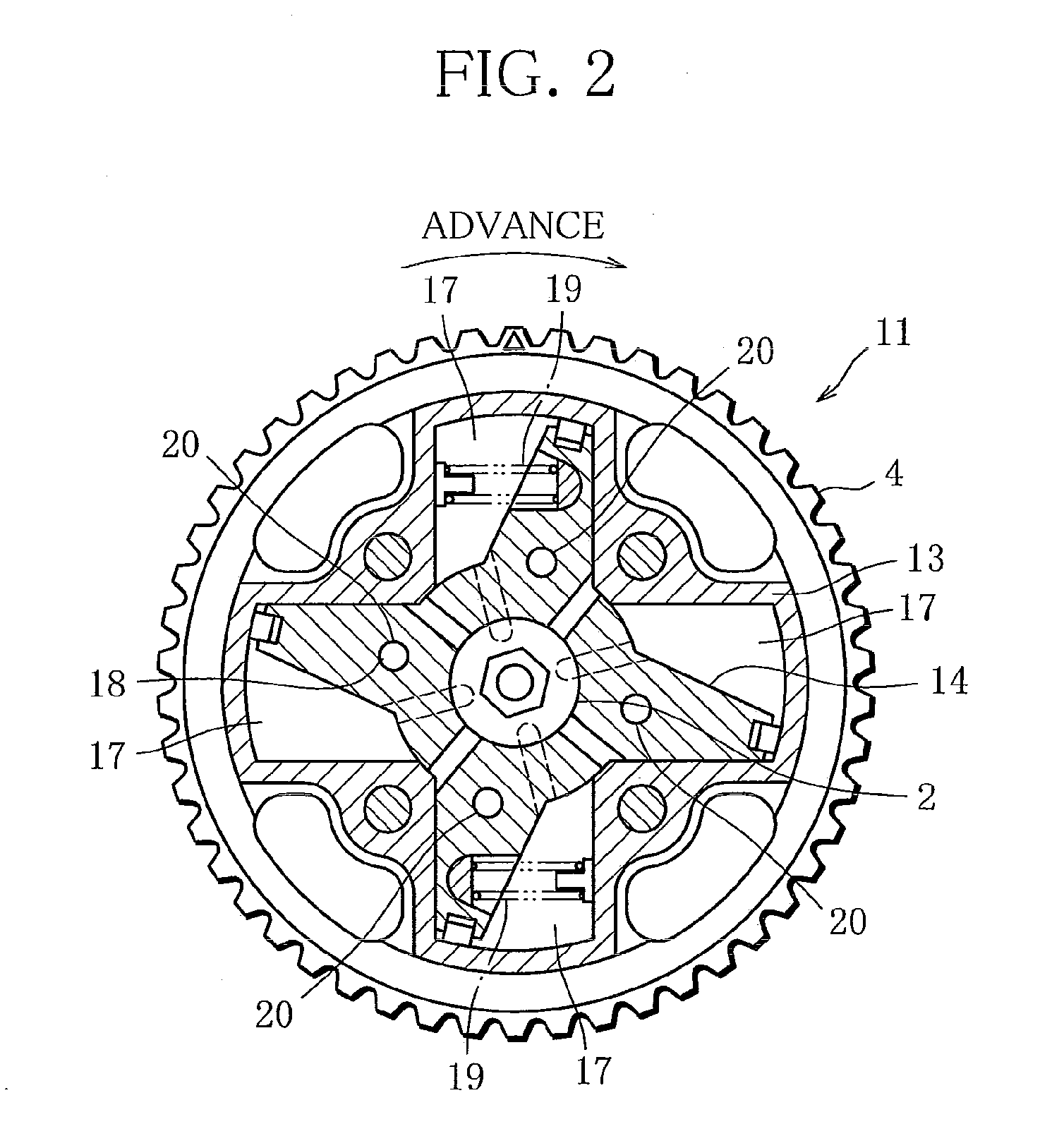
[0020]The variable valve gear of the present embodiment is used for the valve train t...


PUM


Abstract

Disclosed is a variable valve gear comprising a camshaft phase change mechanism, which variably controls a phase of an intake cam with respect to a crankshaft, and a variable valve lift mechanism, which changes an opening timing of an intake valve more than a closing timing and basically continuously varies a lift and an open period of the intake valve. The lift and the open period are set lest the intake valve interfere with a piston of an engine, with the phase controlled to be most advanced by the camshaft phase change mechanism and the lift controlled to be maximal by the variable valve lift mechanism.

Description

BACKGROUND OF THE INVENTION[0001]1. Field of the Invention[0002]The present invention relates to a variable valve gear for an internal combustion engine, capable of changing the lift and the opening and closing timings of an intake valve.[0003]2. Description of the Related Art[0004]Conventionally, a variable valve lift mechanism for changing the lifts of intake and exhaust valves and a variable valve timing mechanism for changing the opening and closing timings (phases) of the valves are known as variable valve gears for internal combustion engines. An increasing number of modern internal combustion engines are equipped with both these mechanisms in order to further improve the fuel efficiency and output performance.[0005]In one such internal combustion engine provided with both the variable valve lift mechanism and the variable valve timing mechanism, a piston may interfere with the intake or exhaust valve near its top dead center when the lift or the opening and closing timings ar...

Claims


Application Information

Patent Timeline
Patent Type & Authority Applications(United States)
IPC IPC(8): F01L1/34F16D3/10
CPCF01L1/024F01L1/20F01L1/3442F01L13/0063F01L2001/0537F01L2001/34469F01L2001/34483F01L2105/00F01L2800/16F01L2305/00F01L13/00F01L1/34F02D13/02
Inventor TODA, HITOSHITAKAGAKI, MASAYUKIMURATA, SHINICHI
Owner MITSUBISHI MOTORS CORP
Why Eureka
Try Eureka