Fuel injection control apparatus and fuel injection control method for internal combustion engine

Inactive Publication Date: 2010-05-13
TOYOTA JIDOSHA KK
View PDF6 Cites 20 Cited by
  • Summary
  • Abstract
  • Description
  • Claims
  • Application Information

AI Technical Summary

Benefits of technology

[0023]According to the fuel injection control apparatus and the fuel injection control method as described above, the interval is set so that the deviation of the actual fuel injection amount from the normal fuel injection amount for the subsequent fuel injection falls within the preset permissible range. Therefore, the deviation during the subsequent fuel injection is reduced. Therefore, the accuracy of

Problems solved by technology

However, when the pilot injection is performed, the fuel pressure in the fuel injection valve pulsates.
If the main injection is performed during this period, the amount of fuel actually injected during the main injection may deviate from a normal fuel amount.
On the other hand, an error in the amount of fuel actually injected through main injection with respect to the normal fuel amount is determined in accordance with an interval between pilot injection and main injection.
On the other hand, the error i

Method used


Image

  • Fuel injection control apparatus and fuel injection control method for internal combustion engine
  • Fuel injection control apparatus and fuel injection control method for internal combustion engine
  • Fuel injection control apparatus and fuel injection control method for internal combustion engine

Examples


first embodiment

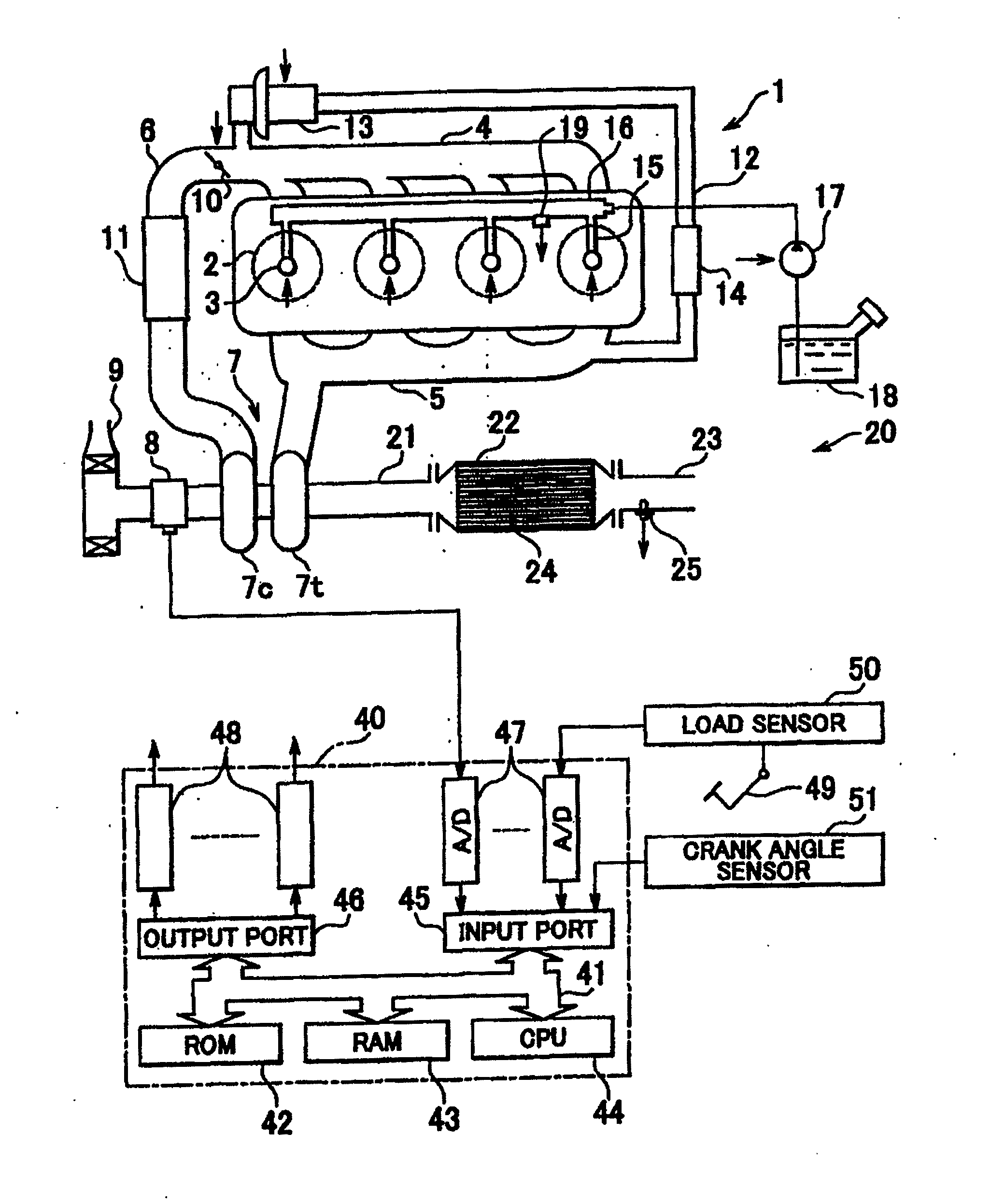
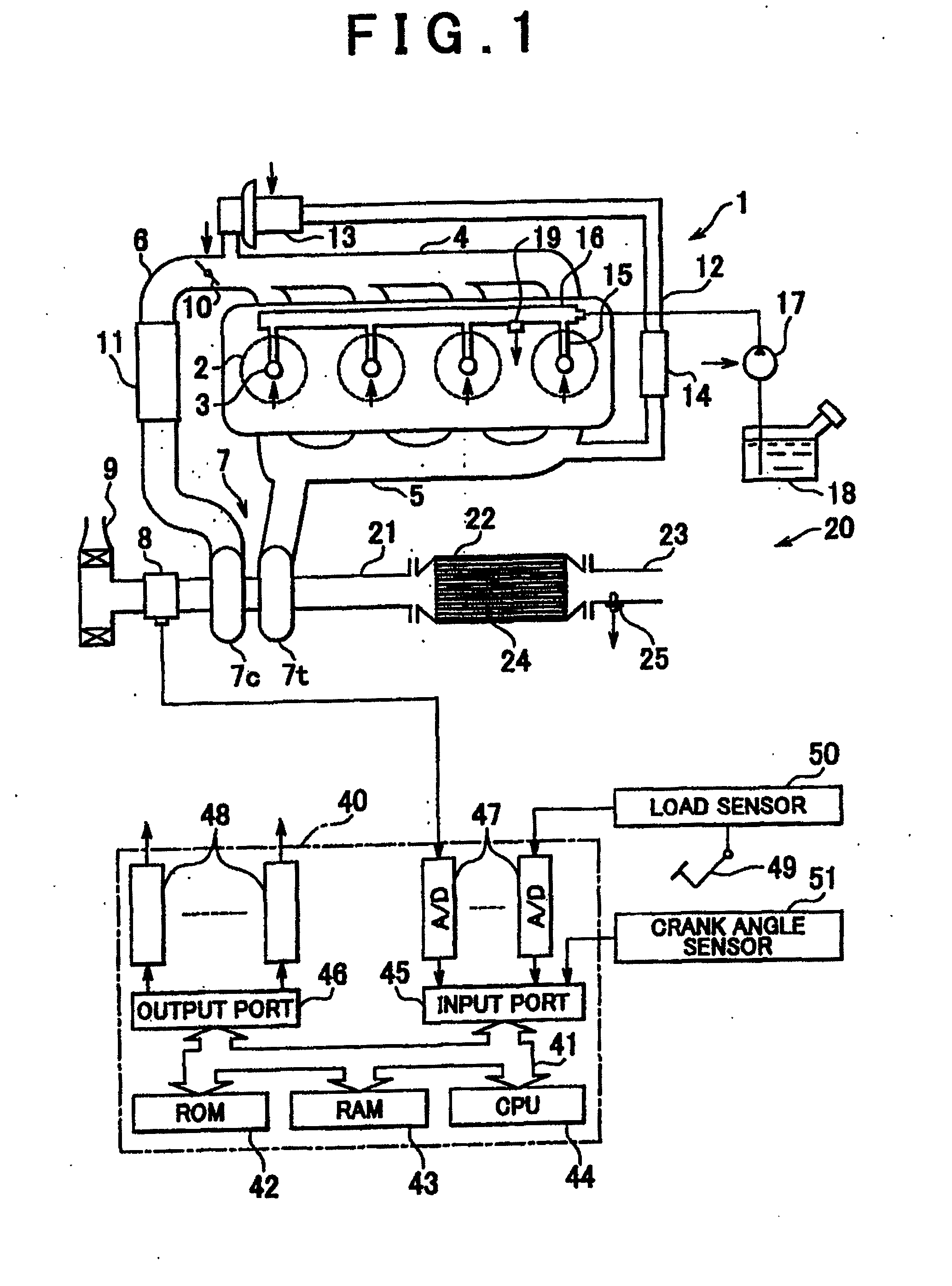
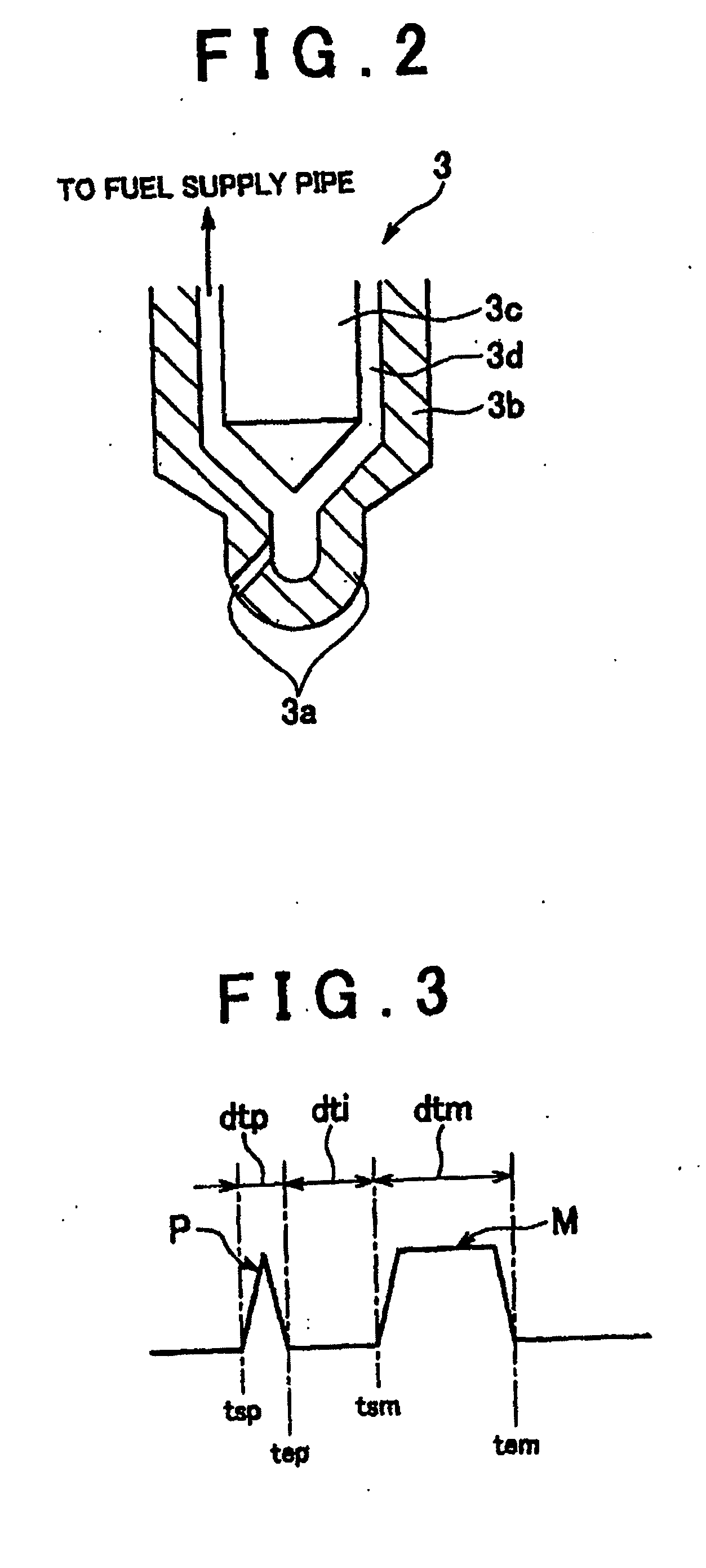
[0063]In the invention, as shown in FIG. 3, main injection M is carried out around a compression top dead center, and pilot injection P is carried out once in a compression stroke prior to main injection M. The outline of a method of setting injection parameters such as an injection start timing, an injection end timing, and an injection time will be described with reference to FIG. 3.

[0064]That is, first of all, a total fuel injection amount Qt (mm3) as an amount of fuel to be supplied to each cylinder 2 from each fuel injection valve 3 per combustion cycle is calculated. The total fuel injection amount Qt is stored in advance in the ROM 42 in the form of a map shown in FIG. 4 as a function of an engine operational state, for example, the required load L and the engine speed Ne. The start timing tsm for main injection M is then calculated. This start timing tsm for main injection M is stored in advance in the

[0065]ROM 42 in the form of a map shown in FIG. 5 as a function of an engi...

third embodiment

[0090]The arrow in FIG. 18 indicates a zero gradient timing tzsx, in other words, one of the zero gradient timings following the main injection M, at which the after fuel injection amount deviation dQa exceeds a predetermined set amount dQa1. Thus, in the invention, the interval dtia is set so that the after-injection A is carried out at the zero gradient timing tzsx, at which the after fuel injection amount deviation dQa is greater than the set value dQa1 as described above.

[0091]As is apparent from the foregoing description, the after fuel injection amount deviation dQa represents the fuel pressure in the fuel injection valve 3 after main injection M. Accordingly, in the third embodiment of the invention, the interval dtia is set so that after-injection A is carried out when the fuel pressure in the fuel injection valve 3 exceeds the predetermined set pressure. In this manner, the injection rate of after-injection A can be enhanced. Therefore, the large after fuel injection amount...

fourth embodiment

[0101]As is the ease with the foregoing embodiments of the invention, when first pilot injection P1 is carried out, the fuel pressure in the fuel injection valve 3 pulsates, and when the second pilot injection P2 is carried out, the fuel pressure in the fuel injection valve 3 pulsates. In the invention, the first interval dti1 is set so that the second pilot injection P2 is started at a zero gradient timing after first pilot injection P1, and the second interval dti2 is set so that the main injection M is started at a zero gradient timing after second pilot injection P2.

[0102]In addition, in the fourth embodiment of the invention, a switchover between the first interval dti1 and the second interval dti2 is made in accordance with the engine operational state.

[0103]That is, as shown in FIG. 24, the first interval dti1 is set to a short first interval dti1 S if the total fuel injection amount Qt is smaller than a first set value Qt1 determined in advance, and to a long first interval ...


PUM


Abstract

A fuel injection valve coupled to a common rail is provided. When fuel injection is carried out, the fuel pressure in the fuel injection valve pulsates. An interval between a pilot injection and a main injection is set so that the main injection is carried out at a zero gradient timing as a timing when the gradient of the fuel pressure in the fuel injection valve after the pilot injection is approximately equal to zero. Owing to a fuel injection control apparatus and a fuel injection control method for an internal combustion engine that perform the above-mentioned control, the fuel injection amount for the subsequent fuel injection following the preceding fuel injection can be reliably held equal to a normal amount.

Description

BACKGROUND OF THE INVENTION[0001]1. Field of the Invention[0002]The invention relates to a fuel injection control apparatus and a fuel injection control method for an internal combustion engine.[0003]2. Description of the Related Art[0004]Conventionally, an internal combustion engine may be equipped with a fuel injection valve that is coupled to a common rail and performs a pilot injection during a compression stroke of the engine and then performs the main injection when the piston is near top dead center in the compression stroke.[0005]However, when the pilot injection is performed, the fuel pressure in the fuel injection valve pulsates. Therefore, there is a brief period where the fuel pressure in the fuel injection valve deviates from a normal fuel pressure. If the main injection is performed during this period, the amount of fuel actually injected during the main injection may deviate from a normal fuel amount.[0006]On the other hand, an error in the amount of fuel actually inj...

Claims


Application Information

Patent Timeline
IPC IPC(8): F02B3/00F02M69/46F02M51/00
CPCF02D41/345F02D41/401F02D2250/04Y02T10/44Y02T10/40
Inventor KOYAMA, TAKASHIOHKI, HISASHIFUJIWARA, KIYOSHIKANEKO, TOMOHIROYAMADA, TAKAHUMI
Owner TOYOTA JIDOSHA KK
Why Eureka
Try Eureka