Insulating spacer for plating inner surface and auxiliary anode unit

a technology of insulating spacer and inner surface, which is applied in the direction of manufacturing tools, electrical-based machining electrodes, machining electrodes, etc., can solve the problems of inability to employ a method, excessive plating on the inner surface side of the outer surface, etc., to prevent and suppress the occurrence of unplated areas, enhance the manufacture of insulating spacers, and prevent the effect of unplated areas

Active Publication Date: 2010-05-13
DAIWA EXCEL
View PDF1 Cites 5 Cited by
  • Summary
  • Abstract
  • Description
  • Claims
  • Application Information

AI Technical Summary

Benefits of technology

[0008]Additionally, since a plurality of unit spacers are coupled so as to compose an insulating spacer, each unit spacer does not need to be unmolded separately from the mold when molding the insulating spacer. This means, pulling out one unit spacer can unmold the whole insulating spacer. Accordingly, the manufacturability in manufacturing the insulating spacer can also be enhanced.
[0009]In addition, as an aspect of the invention, the coupling portion may be in a thin and rod-like shape placed in an eccentric position on the outer surface of the annular plate provided in the end of the unit spacer. According to this configuration, when the insulating spacer is mounted to the auxiliary anode, the surface area of the auxiliary anode to be covered by the unit spacer and the coupling portion can be smaller. This achieves the uniformity of the electrical current distribution on the inner surface area of the tubular object to be plated, and thereby obtaining the uniformity of plating thickness. Furthermore, three or more unit spacers may be coupled, and the coupling portions positioned between each unit spacer may be in the same position when viewed form the axial direction of the unit spacer. With this configuration, the coupling portions in a thin and rod-like shape provided in the eccentric position in the annular plate are linearly-arranged in the axial direction of the unit spacer, and the insulating spacer can therefore bend at a large angle with the coupling portion positioned inner side, and also, can bend in accordance with the sharp-angled bend part of the tubular object to be plated.
[0010]In addition, as another aspect of the invention, three or more annular plates may be provided in each unit spacer, and the annular plates positioned in both ends of the unit spacer may have a smaller external diameter than that of the annular plate positioned in the center. According to this configuration, the unit spacer becomes cylindrical with its central part in the axial direction thick, and therefore, when being bent and inserted into the tubular object to be plated so as to contact with the inner surface of the tubular object to be plated, the outer circumferences of the most protruding center and both ends are locally point-contacted with the inner circumferential surface of the tubular object to be plated, and thereby preventing and suppressing occurrence of an unplated area in the inner surface plating.
[0011]According to the present invention, the auxiliary anode unit used for plating the inner surface of a tubular and curved object to be plated can be expected to be manufactured with good workability.

Problems solved by technology

Here, when the object to be plated is a tube, plating on the inner surface side thereof becomes excessively insufficient compared to the outer surface side, since the inner surface is hidden from the electrode and the electrical current is therefore insufficient.
In that case, when the tube is a straight tube, the auxiliary anode may be passed concentrically inside of its hollow as vertically immersing the straight tube, however, this method cannot be employed when the tube is a bent tube curved in the middle thereof.

Method used


Image

  • Insulating spacer for plating inner surface and auxiliary anode unit
  • Insulating spacer for plating inner surface and auxiliary anode unit
  • Insulating spacer for plating inner surface and auxiliary anode unit

Examples


embodiment 1

[0022]In what follows, Embodiment 1 of the present invention is described as referring to FIGS. 1 to 5. In this embodiment, a case for galvanizing a filler pipe 1 as a pipe at a gasoline tank inlet in a vehicle is shown by example. This filler pipe 1 is, as shown in FIG. 5, made from a steel product and formed in a bent tube shape, wherein the head of the straight part continuing to an inlet 2 is squeezed and then bent obtusely in one direction, and then, the end is further bent back at nearly a right angle.

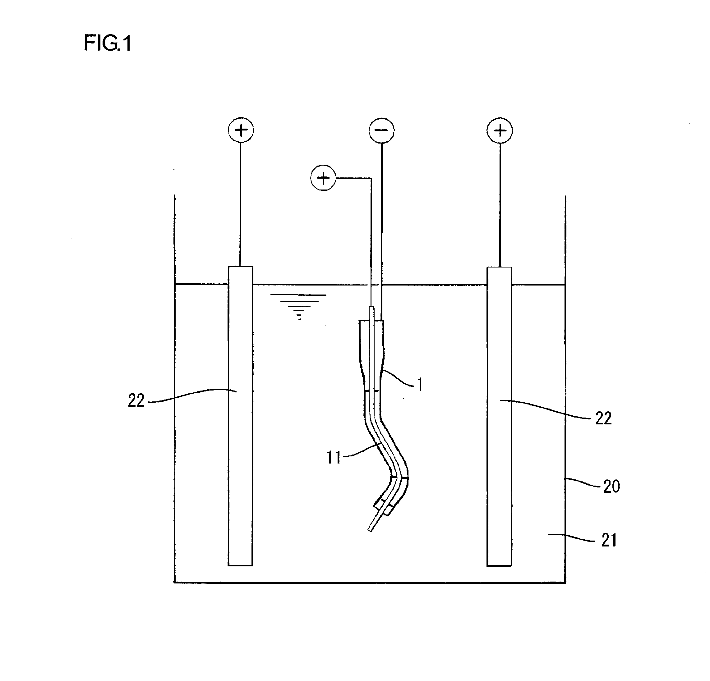
[0023]The filler pipe 1 as mentioned above is suspended via a hanger not shown and delivered on a line, with the auxiliary anode unit 10 as explained later in details inserted thereinto. While being delivered, the filler pipe 1 is sequentially subjected to: pretreatment processes such as degreasing and washing, galvanizing process, washing, chromating, aftertreatment processes such as drying, and then is taken out as a plated product.

[0024]A plating bath 20 is used for the galvan...

embodiment 2

[0042]As referring now to FIGS. 6 and 7, Embodiment 2 of the present invention is described. The difference from Embodiment 1 lies in the change of the configuration of the unit spacer, and others are the same as the above embodiment. The same numerals are allotted to the same elements as those in the above-mentioned embodiment, and description thereof is omitted.

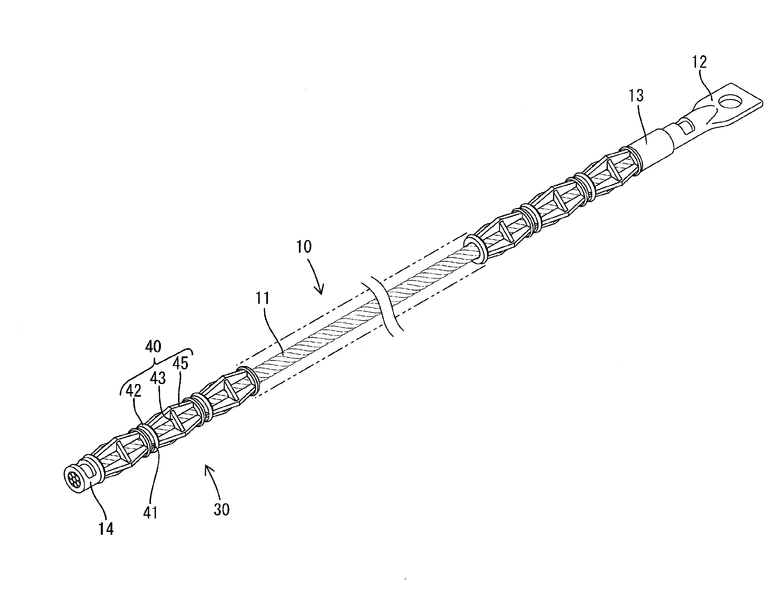
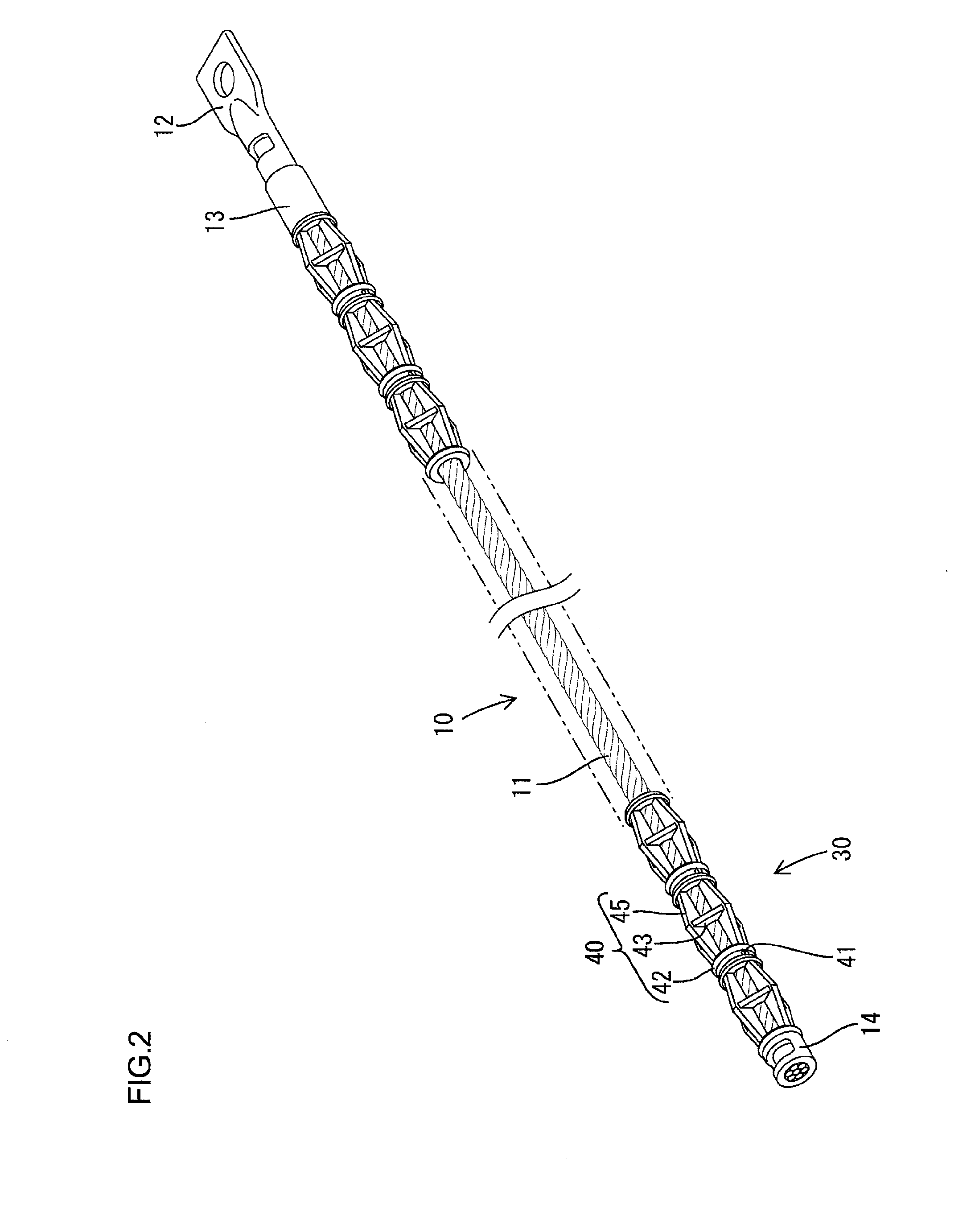
[0043]An unit spacer 50 is composed of two end annular plates 42 in a circular shape and four coupling frames 55 in a plate shape integrally molded with the end annular plate 42 at angle intervals of 90 degrees in a manner so as to connect the end annular plates 42. The section continuing to the inner circumference side of the end annular plate 42 in each coupling frame 55 extends linearly in the axial direction of the unit spacer 50. On the other hand, the section continuing to the outer circumference side of the end annular plate 42 extends in an arc shape toward the pointed end part 57 positioned in the center in the len...

embodiment 3

[0045]As referring now to FIGS. 8 and 9, Embodiment 3 of the present invention is described. The difference from Embodiments 1 and 2 lies in the further change of the configuration of the unit spacer, and others are the same as the above embodiments. The same numerals are allotted to the same elements as those in the above-mentioned embodiment, and description thereof is omitted.

[0046]An unit spacer 60 is constituted in a manner that four coupling frames 45 each forming a plate shape are provided so as to connect two end annular plates 62 in a circular shape. The section continuing to the inner circumference side of the end annular plate 62 in each coupling frame 45 extends linearly in the axial direction of the unit spacer 60, while the section continuing to the outer circumference side of the end annular plate 62 forms a crest shape with the largest width at the center in the length direction in the coupling frame 45. Moreover, provided in the joint part between the end annular pl...


PUM

PropertyMeasurementUnit
angleaaaaaaaaaa
flexibleaaaaaaaaaa
shapeaaaaaaaaaa

Abstract

An insulating spacer 30 comprises a plurality of unit spacers 40, and a flexible coupling portion 41 for coupling the unit spacers 40 along the axial direction thereof, wherein the unit spacer 40 comprises a plurality of annular plates 42 and 43 each having an insertion hole 44 for inserting the auxiliary anode 11, and a coupling frame 45 for coupling the annular plates 42 and 43 in the axial direction of the auxiliary anode 11 while opening the outer circumference side thereof. The auxiliary anode unit 10 is constituted by inserting the insulating spacer 30 into the auxiliary anode 11, and since each unit spacer 40 is coupled, the distal end of the auxiliary anode 11 is naturally located in proximity to the insertion hole 44 provided in the next unit spacer 40 when the auxiliary anode 11 penetrates one unit spacer 40. Accordingly, the auxiliary anode 11 can be inserted into the insulating spacer 30 by series of works, and as a result, the auxiliary anode unit 10 can be manufactured with good workability.

Description

TECHNICAL FIELD[0001]The present invention relates to an insulating spacer and an auxiliary anode unit preferably used for plating the inner surface of a tubular object to be plated, particularly a bent tube.BACKGROUND ART[0002]The electroplating is generally conducted by immersing an electrode and an object to be plated into a plating liquid containing a plating metal dissolved therein, and then applying an electrical current between both parties, the electrode as anode and the object to be plated as cathode. Here, when the object to be plated is a tube, plating on the inner surface side thereof becomes excessively insufficient compared to the outer surface side, since the inner surface is hidden from the electrode and the electrical current is therefore insufficient. On the other hand, as a countermeasure against the above, an auxiliary anode has been disposed in the tube so as to improve the electrical current distribution. In that case, when the tube is a straight tube, the auxi...

Claims


Application Information

Patent Timeline
Patent Type & Authority Applications(United States)
IPC IPC(8): C25B11/00
CPCC25D7/04C25D17/12
Inventor MIZUNO, CHIKANORI
Owner DAIWA EXCEL
Why Eureka
Try Eureka