Electrophoretic chip and a method of electrophoresis

a technology of electrophoresis and electrophoresis, which is applied in the field of electrophoresis electrophoresis, can solve the problems of obstructing the application of the voltage by the supplier of the separation medium, increasing the cost of the apparatus, and the mechanism complicating the apparatus, so as to reduce the cost of the apparatus, and increase the positional accuracy

Active Publication Date: 2010-05-13
SHIMADZU CORP
View PDF7 Cites 4 Cited by
  • Summary
  • Abstract
  • Description
  • Claims
  • Application Information

AI Technical Summary

Benefits of technology

[0021]As previously described, in the electrophoretic chip according to the present invention, the opening for injecting a separation medium to the channel is provided separately from the sample inlet and the sample outlet. Therefore, in the method for electrophoresis using this electrophoretic chip, with the separation medium supplier for injecting the separation medium being connected to the second opening, electrophoresis in the separation channel portion can be performed by applying a voltage between the first opening and the third opening. That is, after filling the channel with the separation medium, the separation medium supplier is not necessary to be disconnected from the second opening both at the times of injecting a sample into the separation channel and of performing electrophoresis. In other words, it is possible to realize the state (“online state”) in which the separation medium supplier is always connected to the channel.
[0022]This brings about the following advantages to the electrophoretic chip according to the present invention, compared to the conventional configurations in which the separation medium supplier is required to be disconnected and substantially moved from the electrophoretic chip every time the injection of a sample and electrophoresis are performed.
[0023]That is, there is no need of providing a drive mechanism for moving the separation medium supplier by a substantial distance and with a high positional accuracy, so that the electrophoresis apparatus using this electrophoretic chip is simplified and the cost of the apparatus can be reduced. In addition, since the separation medium supplier can be fixed to the electrophoretic chip, a high-precision seal mechanism indispensable to connecting and disconnecting them is unnecessary, and an inexpensive seal mechanism can be used to reduce the cost of the apparatus.
[0024]Since the displacement in connecting the separation medium supplier to the electrophoretic chip is of no regard, the dead volume between the end of the injection nozzle and the opening can be decreased. Moreover, the separation medium supplier can be kept connected to the electrophoretic chip while performing electrophoresis, so that the separation medium may not be dehydrated and bubbles may not be introduced in it. These all minimize the waste of separation medium, and the use of the separation medium can be decreased to reduce the analysis cost.
[0025]In the electrophoretic chip according to the present invention, the separation channel portion and the separation medium introduction channel portion are connected without disposing any element such as a connector. Therefore, the channels need not be connected with a high-pressure seal which was necessary for a previously described capillary electrophoresis apparatus.
[0026]In a method for electrophoresis using the electrophoretic chip according to the present invention, the separation medium is filled in the separation channel portion as follows. With the third opening opened, the separation medium is injected from the second opening by the separation medium supplier to fill the separation medium introduction channel portion with the separation medium. Then, with the third opening closed, the separation medium is injected from the second opening by the separation medium supplier to introduce the separation medium in the separation channel portion.

Problems solved by technology

In the aforementioned configuration, when the voltage is applied between the electrodes after the buffer is filled in the reservoir, the separation medium supplier obstructs the application of the voltage.
Providing such a movement mechanism complicates the apparatus and increases its cost.
This brings about a large dead volume between the end of the nozzle and the opening, which requires an additional amount of separation medium, and increases the analysis cost.
In this respect, also, an additional amount of separation medium is necessary, which increases the analysis cost.
This increases the use of the buffer, which may increase the analysis cost.
However, such a configuration has a disadvantage in that, since a high pressure is applied to the joint of the separation channel and the separation medium introduction channel when injecting the separation medium or at other processes, a high-pressure seal is necessary to resist such a pressure.

Method used


Image

  • Electrophoretic chip and a method of electrophoresis
  • Electrophoretic chip and a method of electrophoresis
  • Electrophoretic chip and a method of electrophoresis

Examples


Embodiment Construction

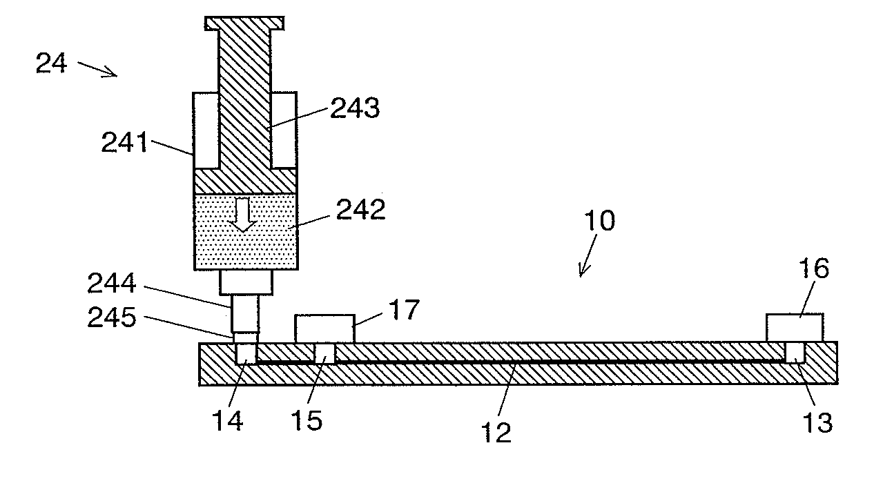
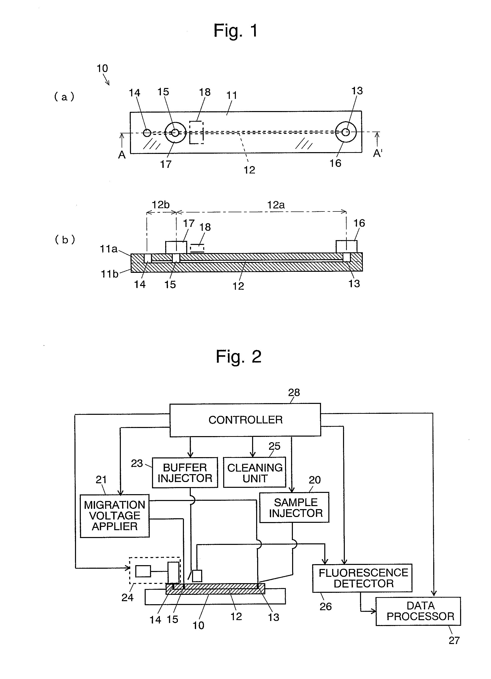
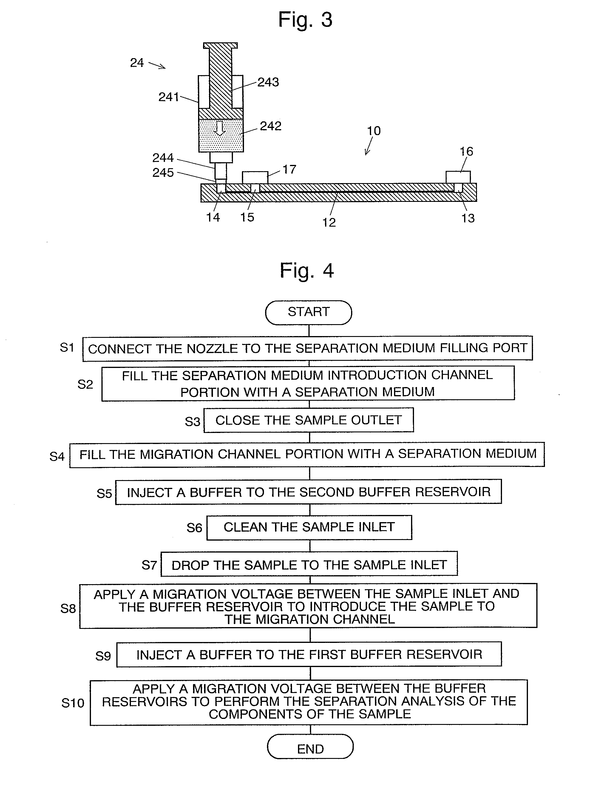
[0061]First, the structure of one embodiment of the electrophoretic chip according to the present invention will be described with reference to FIG. 1. FIG. 1(a) is a top plain view of the electrophoretic chip 10 according to the present embodiment, and FIG. 1(b) is a sectional view at line A-A′ in FIG. 1(a).

[0062]The electrophoretic chip 10 has a substrate 11 having the shape of a long, flat parallelepiped and in which a pair of transparent flat plates 11a and 11b such as a glass plate, silica glass plate, or other plate are bonded. On the lower face of the upper transparent flat plate 11a, a straight line groove is formed, by etching for example. At both ends of the groove, cylindrical through-holes are bored, and at a position midway, but closer to one of the ends, on the groove, a third cylindrical through-hold is bored. The groove has a width of about 10 to 100 μm, and a depth of about 5 to 50 μm.

[0063]The pair of transparent flat plates 11a and 11b are bonded with the groove f...


PUM

PropertyMeasurementUnit
depthaaaaaaaaaa
widthaaaaaaaaaa
voltage V1aaaaaaaaaa

Abstract

A channel (12) is formed inside a transparent substrate (11), and the two ends are respectively connected to a sample inlet (13) and a separation medium filling port (14) both open to outside, and a sample outlet (15) which is open to outside is provided on the channel (12). The portion between the sample inlet (13) and the sample outlet (15) is a separation channel portion (12a), and the portion between the sample outlet (15) and the separation medium filling port (14) is a separation medium introduction channel portion (12b). A separation medium supplier is connected to the separation medium filling port (14) and the separation medium introduction channel portion (12b) is filled with a separation medium. Then a sample is dropped to the sample inlet (13), with the sample medium supplier still connected, to introduce the sample to the separation channel portion (12a). And then, buffer liquid is poured in buffer reservoirs (16) and (17) and a migration voltage is applied to perform a migration analysis. Since an analysis can be repeatedly performed with the sample medium supplier kept connected, it is not necessary to disconnect the supplier from the electrophoretic chip each time a migration is performed.

Description

TECHNICAL FIELD[0001]The present invention relates to an electrophoretic chip which is a device suitable for use in the fields of mainly biochemistry, molecular biology, clinical medicine, and in particular, analysis of DNA and protein, or other fields. The present invention also relates to a method of the electrophoresis using the electrophoretic chip.BACKGROUND ART[0002]Capillary electrophoresis (CE) is a method suitable for the analysis of a biological sample such as peptide, protein, DNA, and sugar. It is also suitable for the optical resolution, isotope separation, and other processes, in which components having similar structures are separated. It is widely used in the application of clinical medicine, pharmaceutical drugs, monitoring of environmental substances, etc. In particular, the apparatus (microchip electrophoresis apparatus) using a microchip in which microchannels are formed by using the photolithography technique and other techniques has come to be much used in rece...

Claims


Application Information

Patent Timeline
Patent Type & Authority Applications(United States)
IPC IPC(8): G01N27/26
CPCG01N27/447G01N2035/00158
Inventor KAJI, TORU
Owner SHIMADZU CORP
Why Eureka
Try Eureka