Phase current estimation apparatus for motor and magnetic pole position estimation apparatus for motor

a technology of phase current estimation and motor, which is applied in the direction of motor/generator/converter stopper, polyphase induction motor starter, dynamo-electric converter control, etc., can solve the problems of inability to quickly perform estimation, inability to improve general versatility, and difficulty in adjusting the modulation scheme, etc., to achieve easy quantitative analysis, easy control, easy control

Inactive Publication Date: 2010-05-13
HONDA MOTOR CO LTD
View PDF1 Cites 15 Cited by
  • Summary
  • Abstract
  • Description
  • Claims
  • Application Information

AI Technical Summary

Benefits of technology

[0015]According to the phase current estimation apparatus for the motor of the second aspect of the present invention, the harmonic components corresponding to the vector components that are obtained by decomposing the command voltage vector can be easily quantitatively analyzed by using mathematical equations. In addition, since the two harmonic components corresponding to the two vector components have the same magnitude and different signs, the sum of the two harmonic components is zero, so that the harmonic components that are generated by decomposing the command voltage vector can be easily controlled.(3) A third aspect of the present invention is a magnetic pole position estimation apparatus including: the phase current estimation apparatus for a motor according to the second aspect of the present invention and an estimation unit that estimates a magnetic pole position of the motor based on a change in an inductance when the harmonic component is applied to the motor.

Problems solved by technology

However, in the inverter apparatus in the related art, there are problems in that only two-phase modulation is an effective modulation scheme, in that it is difficult to cope with the change in the modulation scheme, and in that it is not possible to improve the general versatility.
Therefore, there is a problem in that the estimation cannot be promptly performed.
In addition, since harmonic components (that is, the differences between the vectors obtained by the decomposition and the command voltage vector) corresponding to one PWM, which are generated by decomposing the command voltage vector into two vectors in the PWM periods of two first and second time intervals for securing a desired length of a pulse width are not quantitatively analyzed by using mathematical equations, there is a problem in that it is not possible to improve the estimation accuracy of the phase currents by controlling the harmonic components.

Method used


Image

  • Phase current estimation apparatus for motor and magnetic pole position estimation apparatus for motor
  • Phase current estimation apparatus for motor and magnetic pole position estimation apparatus for motor
  • Phase current estimation apparatus for motor and magnetic pole position estimation apparatus for motor

Examples


Embodiment Construction

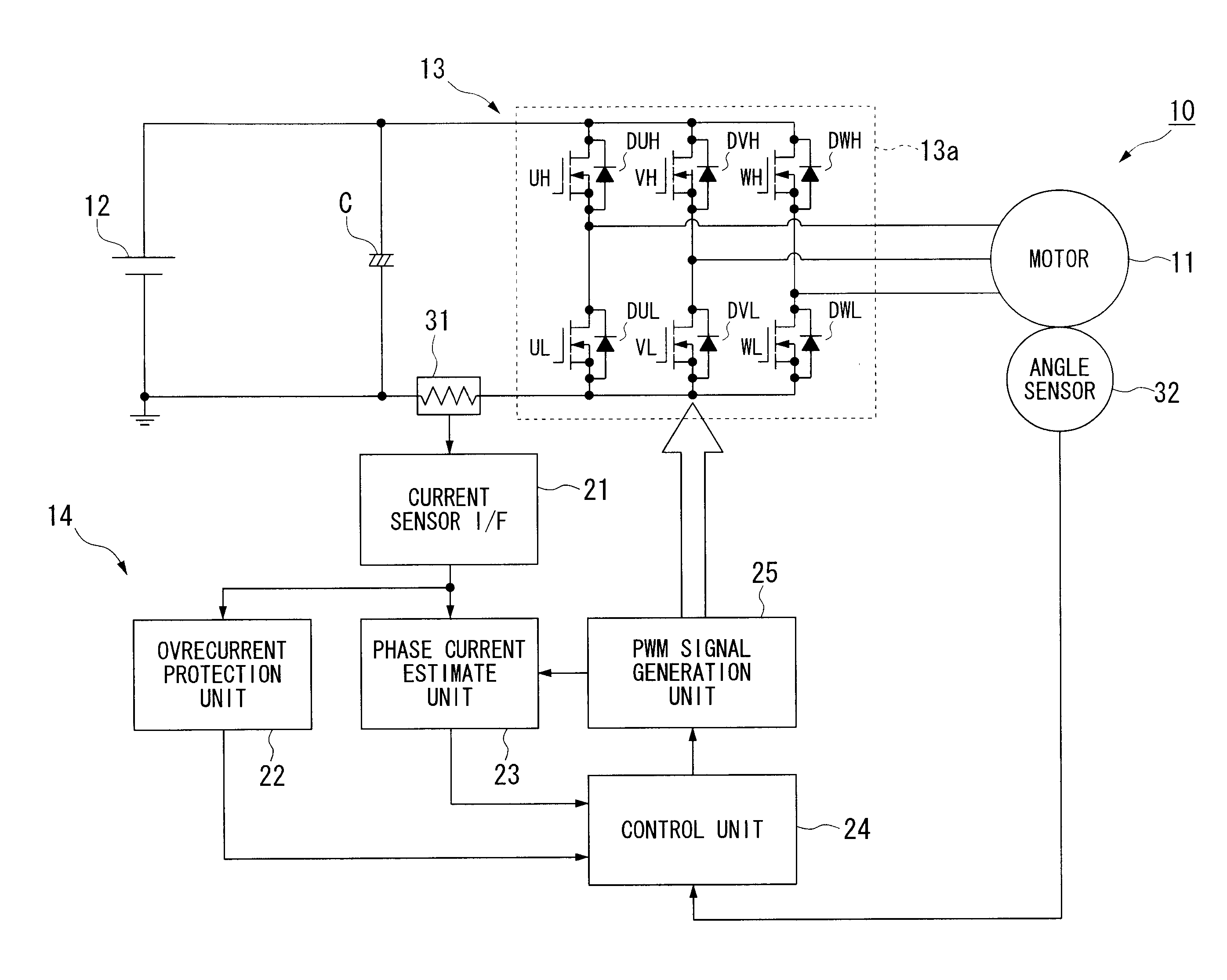
[0029]Hereinafter, a phase current estimation apparatus for a motor and a magnetic pole position estimation apparatus for a motor according to embodiments of the present invention will be described with reference to the accompanying drawings.

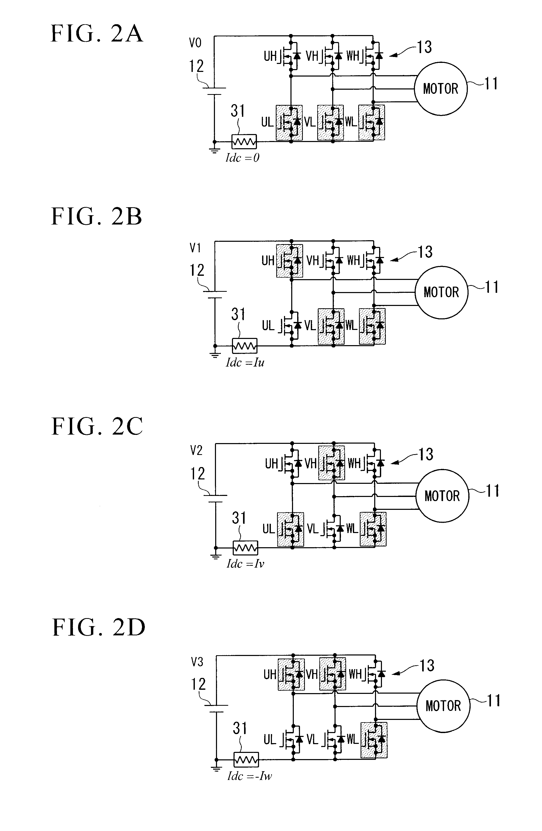
[0030]In the embodiment, the phase current estimation apparatus 10 for a motor (hereinafter, simply referred to as a phase current estimation apparatus 10) estimates phase currents that electrically conduct, for example, a three-phase brushless DC motor 11 (hereinafter, simply referred to as a motor 11). The motor 11 includes a rotator (not shown) having a permanent magnet using a field and a stator (not shown) generating a rotating magnetic field for rotating the rotator.

[0031]As shown in FIG. 1, the phase current estimation apparatus 10 includes, for example, an inverter 13 having a battery 12 as a DC power supply and a motor control unit 14.

[0032]The three-phase (for example, 3 phases of U-phase, V-phase, and W-phase) AC motor 11 is driven by...


PUM


Abstract

A phase current estimation apparatus for a motor capable of suitably improving estimation accuracy of phase currents is provided. The phase current estimation apparatus 10 of the motor includes a control unit 24 that decomposes a command voltage vector Vdq into two vector components V′dq in the case where a magnitude of the command voltage vector Vdq is less than a predetermined lower limit voltage Vlow, so that the command voltage vector Vdq is allowed to have the magnitude equal to or more than the predetermined lower limit voltage Vlow for every two adjacent periods in units of a period of a carrier signal and to have the phase outside a predetermined phase range including phases of reference voltage vectors. Accordingly, the control unit 24 can quantitatively analyze harmonic components, which are generated by decomposing the command voltage vector Vdq into the two vector components V′dq, by using mathematical equations.

Description

BACKGROUND OF THE INVENTION[0001]1. Field of the Invention[0002]The present invention relates to a phase current estimation apparatus for a motor and a magnetic pole position estimation apparatus for a motor.[0003]The priority is claimed on Japanese Patent Application No. 2008-291090, filed Nov. 13, 2008, the content of which are incorporated herein by reference.[0004]2. Description of the Related Art[0005]In the related art, for example, there is disclosed an inverter apparatus that outputs two first and second reference voltage vector components, of which phases are different by 60 degrees and from which a command voltage vector can be generated, in a first time interval of one PWM period (one period of a carrier wave) and outputs two third and fourth reference voltage vector components, of which phases are different by 180 degrees with respect to the first and second reference voltage vector components in a second time interval of one PWM period consecutively following the first ...

Claims


Application Information

Patent Timeline
Patent Type & Authority Applications(United States)
IPC IPC(8): H02P27/06H02P23/07H02P25/022H02P27/08
CPCH02P21/0003
Inventor AKIYAMA, MASAHIKO
Owner HONDA MOTOR CO LTD
Why Eureka
Try Eureka