Magnetic resonance imaging apparatus

a magnetic resonance imaging and apparatus technology, applied in the direction of reradiation, measurement using nmr, instruments, etc., can solve the problems of not disclosing a method of regenerating the clock signal or transmitting the sampling clock signal by radio

Active Publication Date: 2010-05-13
TOSHIBA MEDICAL SYST CORP
View PDF16 Cites 59 Cited by
  • Summary
  • Abstract
  • Description
  • Claims
  • Application Information

AI Technical Summary

Problems solved by technology

In the above-mentioned general structure, the cable is often obstructive to operators and / or operations.
Since such a highly accurate oscillator has a large size, if it is provided in the probe unit, the probe unit is inevitably increased in size and weight, which is a significant load on a subject.
However, this publication does not disclose a method of transmitting the sampling clock signal by radio or a method of regenerating the clock signal from a received signal.

Method used


Image

  • Magnetic resonance imaging apparatus
  • Magnetic resonance imaging apparatus
  • Magnetic resonance imaging apparatus

Examples


first embodiment

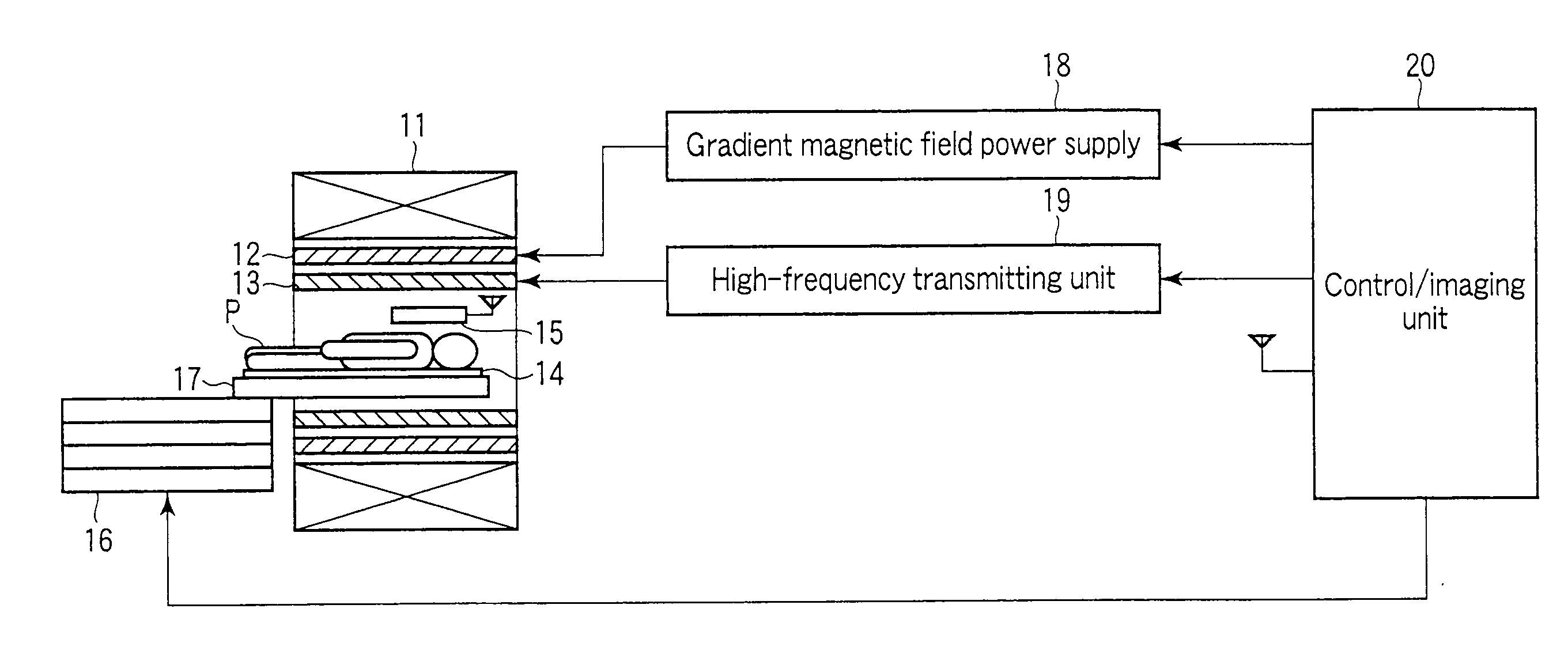
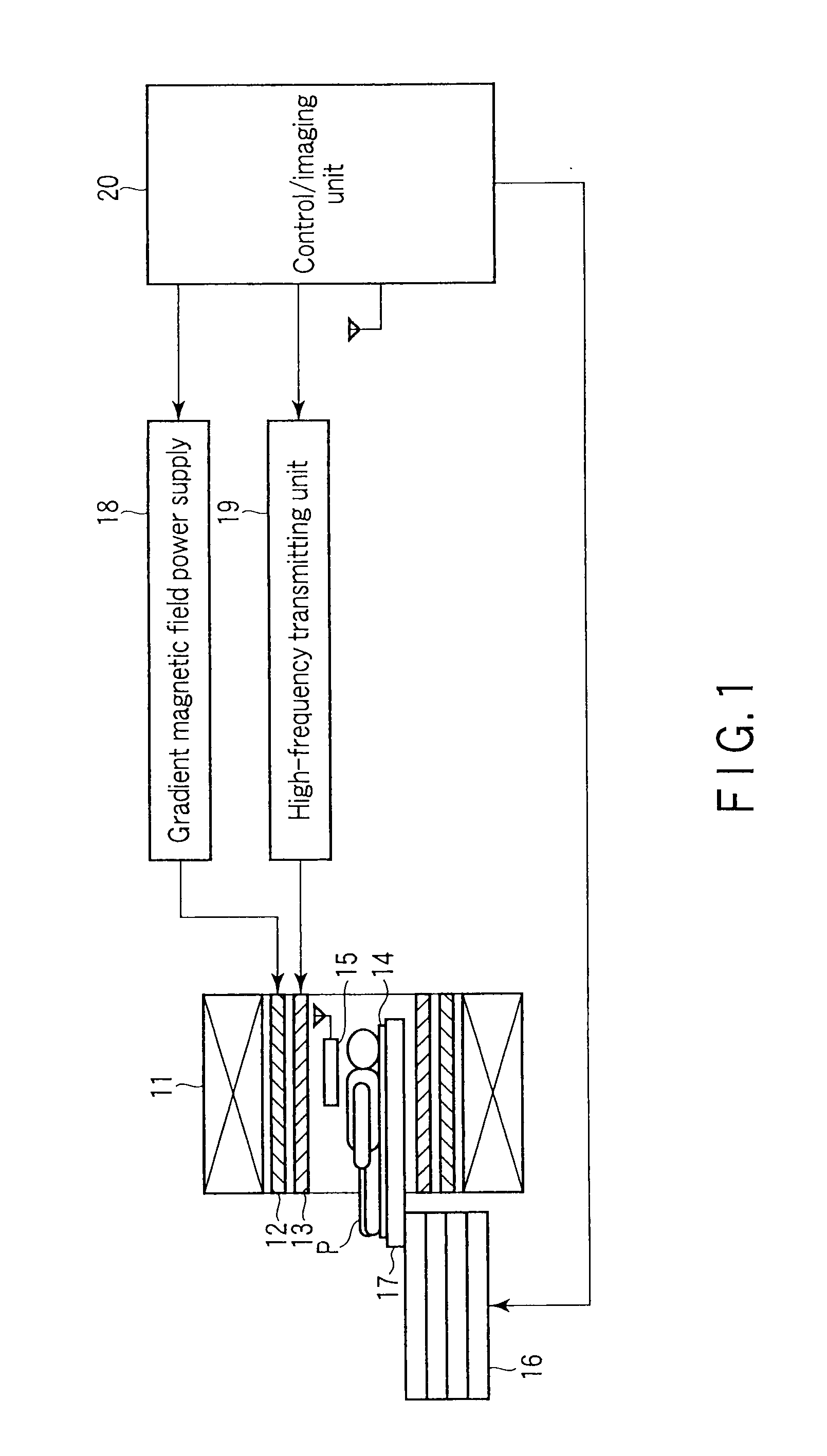
[0037]FIG. 1 shows an MRI apparatus according to a first embodiment. A magnetostatic field magnet 11, a gradient coil 12, an RF coil unit 13, a probe unit 14, a probe unit 15, and a top panel 17 included in a bed 16 are contained in a so-called gantry. The bed 16 is movable, and its position is controlled by a bed position controller described later. A gradient magnetic field power supply 18 is connected to the gradient coil 12, and a high-frequency transmitting unit 19 is connected to the RF coil unit 13. The probe unit 14 is connected to a control / imaging unit 20 via a wired channel (not shown). The other probe unit 15 is connected to the control / imaging unit 20 via a wireless channel.

[0038]The magnetostatic field magnet 11 is a hollow cylindrical member and is configured to generate a uniform magnetostatic field. A permanent magnet, superconductive magnet or the like is used as the magnetostatic field magnet 11. The gradient coil 12 is a hollow cylindrical member and is formed of...

second embodiment

[0103]A description will now be given of a second embodiment. The MRI apparatus of the second embodiment has substantially the same configuration as the first embodiment shown in FIG. 1. FIG. 14 shows a wireless probe unit 15 and control / imaging unit 20 employed in the second embodiment.

[0104]In FIG. 14, elements similar to those of the first embodiment are denoted by corresponding reference numbers, and only different elements will be described. In the second embodiment, the clock signal generator 205 and the first type multiplier 206 are replaced with a variable phase clock generator 210, and a bed position controller 301 and a phase calculator 302 are provided in the probe unit 15. The second embodiment can prevent phase shifting during acquisition of a magnetic resonance signal, using a clock signal phase compensation function that will be described later.

[0105]The receiving antenna 107 of the probe unit 15 is located on a bed 16 controlled by the bed position controller 301. Th...


PUM


Abstract

An apparatus including a probe unit and a control / imaging unit, the probe unit including a converter converting a sampled magnetic-resonance signal into a digital signal, a first transmitter converting the digital signal into a first-radio signal, a first receiver receiving a second-radio signal, and performing detection on the second-radio signal to obtain a first-received signal, and a clock-regeneration unit regenerating a clock component from the first-received signal to generate a regenerated-clock signal, the control / imaging unit including a second-receiver receiving the first-radio signal to obtain a second-received signal, a data processor performing data processing on the second-received signal in synchronism with a reference-clock signal to obtain a video signal, and a second transmitter including a modulator modulating a carrier wave using the reference-clock signal, the second transmitter converting the reference-clock signal into the second-radio signal and transmitting the second-radio signal through the second-wireless channel.

Description

CROSS-REFERENCE TO RELATED APPLICATIONS[0001]This application is based upon and claims the benefit of priority from prior Japanese Patent Application No. 2008-288990, filed Nov. 11, 2008, the entire contents of which are incorporated herein by reference.BACKGROUND OF THE INVENTION[0002]1. Field of the Invention[0003]The present invention relates to a magnetic resonance imaging apparatus for transmitting a magnetic resonance signal and a clock signal by radio.[0004]2. Description of the Related Art[0005]In magnetic resonance imaging (MRI) apparatuses, a detection coil for detecting a magnetic resonance signal is placed in the imaging space of a gantry, along with a subject. The magnetic resonance signal detected by the detection coil is transmitted to a main unit (hereinafter referred to as “a control / imaging unit”) via a cable led from the interior of the imaging space to the outside of the gantry. The control / imaging unit executes imaging by performing, on the detected magnetic res...

Claims


Application Information

Patent Timeline
Patent Type & Authority Applications(United States)
IPC IPC(8): G01R33/44
CPCG01R33/3607G01R33/3692G01R33/3621
Inventor NAKANISHI, TOSHIYUKIAKITA, KOJIKASAMI, HIDEOSEKIGUCHI, TAKAHIRO
Owner TOSHIBA MEDICAL SYST CORP
Why Eureka
Try Eureka