Unitized cooling module for laser diode array

Inactive Publication Date: 2010-05-13
METAL INDS RES & DEV CENT
View PDF3 Cites 24 Cited by
  • Summary
  • Abstract
  • Description
  • Claims
  • Application Information

AI Technical Summary

Benefits of technology

[0011]The unitized cooling module for a laser diode array of the present invention is easily assembled, repaired, and expanded, and has the effect of pressing fit. Furthermore, the unitized cooling module for a laser diode array of the present in

Problems solved by technology

After the laser diodes 13 are powered on, the temperature thereof suddenly rises due to the high current, and thus, the light-emitting quality is unstable.
However, the main disadvantage of the conventional high-density packaged coo

Method used


Image

  • Unitized cooling module for laser diode array
  • Unitized cooling module for laser diode array
  • Unitized cooling module for laser diode array

Examples


Embodiment Construction

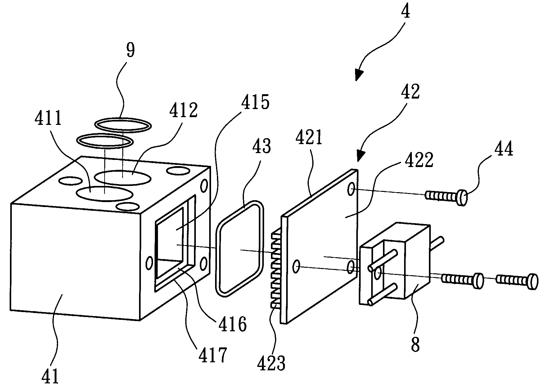
[0019]FIG. 3 is a schematic view of a cooling module for a laser diode array according to a first embodiment of the present invention, FIG. 4 is an exploded view of a cooling unit according to the first embodiment of the present invention, and FIG. 5 is a top view of the cooling unit according to the first embodiment of the present invention. As shown in FIGS. 3 and 4, the unitized cooling module for a laser diode array 3 according to the first embodiment of the present invention has a plurality of cooling units 4, a cooling source 5, a sensing device 6, and a flow controller 7.

[0020]In this embodiment, the cooling module of the present invention is a stacked cooling module for a laser diode array 3, so as to solve the heat-dissipating problem of a high power laser system having a plurality of laser diodes 8. Each cooling unit 4 is used to cool the corresponding laser diode 8 and keep the temperature of the laser diode 8 within a set range.

[0021]As shown in FIGS. 3 to 5, each coolin...


PUM


Abstract

The unitized cooling module for a laser diode array of the invention has at least one cooling unit. The cooling unit has an inlet main channel, an outlet main channel, an inlet subchannel, an outlet subchannel and a chamber. The inlet subchannel connects the inlet main channel and the chamber, and the outlet subchannel connects the outlet main channel and the chamber. A heatsink element carrying a laser diode seals the chamber. With a cooling source flowing through the interior of the cooling unit, the heat produced by the laser diode is removed. Thus, the unitized cooling module of the invention is easily assembled, repaired and expanded, and has the effect of pressing fit. Furthermore, the unitized cooling module of the invention can be arranged and designed according to the heat produced by the laser diode to remove the heat from the laser diode, so that the performance of the unitized cooling module is ensured.

Description

BACKGROUND OF THE INVENTION[0001]1. Field of the Invention[0002]The present invention relates to a cooling module for a laser diode array, in particular, to a unitized cooling module for a laser diode array.[0003]2. Description of the Related Art[0004]A conventional laser diode array mainly adopts an aluminum alloy heatsink module for heat dissipation. However, different heatsink module designs are provided to match the powers of various high power laser diode array.[0005]FIG. 1 is a schematic view of a conventional cooling module. The conventional cooling module 1 includes an aluminum alloy substrate 11 with a plurality of heatsink fins 111 and a fan 12. In the conventional art, a plurality of high power laser diodes 13 is configured on the aluminum alloy substrate 11. The heat produced by the high power laser diodes 13 is conducted to the aluminum alloy substrate 11, and the fan 12 drives air through the heatsink fins 111 so as to dissipate the heat.[0006]The conventional cooling ...

Claims


Application Information

Patent Timeline
IPC IPC(8): H01S3/04H01S5/023H01S5/0233
CPCH01S5/02236H01S5/40H01S5/02423H01S5/024H01S5/023H01S5/0233H01S5/0235
Inventor WU, XIN-YI
Owner METAL INDS RES & DEV CENT
Why Eureka
Try Eureka