Method for deriving parasitic signals from modulated digital signals

Active Publication Date: 2010-05-13
BULL SA
View PDF3 Cites 0 Cited by
  • Summary
  • Abstract
  • Description
  • Claims
  • Application Information

AI Technical Summary

Benefits of technology

[0025]The object of the invention is therefore to provide a method that enables all parasitic signals that influence a transmission of modulated digital signals to be derived, including those

Problems solved by technology

These advantages are offset by disadvantages such as susceptibility to interference and lesser efficiency, so that altered modulation methods such as quadrature amplitude modulation (QAM) are now used in many applications.
Technically, the FSK is normally realized, for example, by two oscillators that can be switched on and off in turn, but this means that the changing phase position in the output signal becomes a disadvantage.
The problem with PSK is precise phase-synchronous tuning of the receiver, and this means that this method of modulation is not well suited to types of transmission with large phase errors, such as mobile radio.
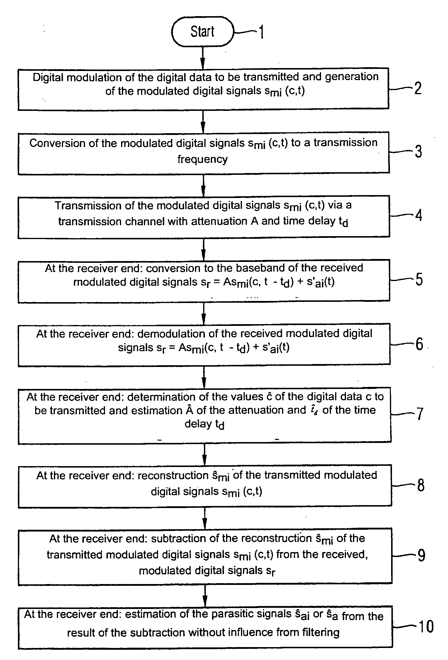
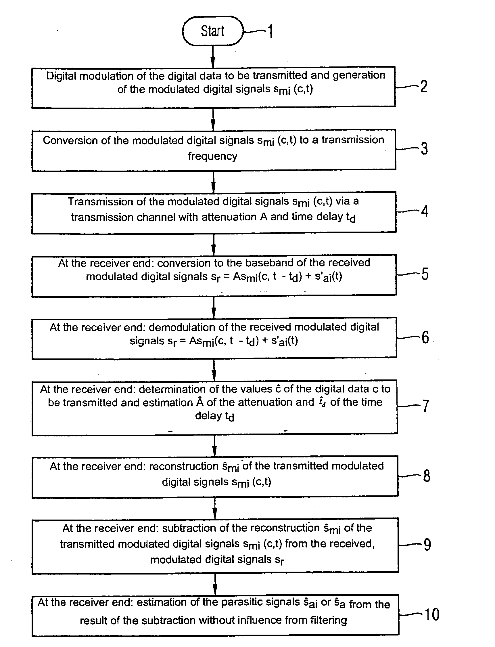
During the transmission, these modulated digital signals can be negatively influenced by parasitic signals.
Such parasitic signals, by means of which the transmission of (digital) information or data mapped in a modulated digital signal is impaired, are, for example, noise or interference
Therefore, interference can cause disturbances in the transmission of (useful) signals, such as modulated digital signals, and the quality of the transmitted, digital data can be substantially impaired.
Particularly with radio technology, interference, that can also include noise, is a widespread problem if this interference, for example, also occurs within a frequency band of the carrier frequency or carrier frequencies, with the range of the e

Method used


Image

  • Method for deriving parasitic signals from modulated digital signals
  • Method for deriving parasitic signals from modulated digital signals
  • Method for deriving parasitic signals from modulated digital signals

Examples


Embodiment Construction

[0036]The method begins with an initial step 1. In a second method step 2, a modulated digital signal sm is generated by digital modulation (e.g. PSK, Q-PSK, QAM, etc.) from digital data to be transmitted, by using a modulation schema. In doing so, for example, the modulated digital signal sm can be represented as a linear combination of N signals sm1, sm2, . . . , smN with a specific modulated signal smi being determined by an index i=1, 2, . . . , N. Each of the modulated digital signals smi in this case corresponds to specific data c, with it being possible for the modulated digital signals smi, for example, to be also represented as functions smi(c, t) with the parameters c and t for a time characteristic and it being assumed that the signals smi(c, t) are, for example, interference-free or ideal.

[0037]In a third method step 3, the modulated digital signals smi(c, t) are converted to a transmission frequency before transmission, i.e. the signals smi(c, t) are converted from a ca...


PUM


Abstract

A method for deriving interference signals from modulated, digital signals is provided. The receiver end reconstructs the modulated digital signals sent by a transmitter. These reconstructed modulated digital signals are then subtracted from the received modulated digital signals, and the result of the subtraction is used to estimate the interference signals without influence by prior filtering at the receiver end. By way of example, it is possible to demodulate the interference signals estimated at the receiver end in order to ascertain possible unauthorized carrier frequencies which disturb the regular carrier frequencies, even if the interference signals are not completely in the bandwidth of the regular carrier frequency or carrier frequencies.

Description

CROSS REFERENCE TO RELATED APPLICATIONS[0001]This application is the US National Stage of International Application No. PCT / EP2006 / 066837, filed Sep. 28, 2006, which is incorporated by reference herein in its entirety, and claims the benefit thereof.FIELD OF INVENTION[0002]The invention relates to a method for deriving parasitic signals from modulated digital signals, with each signal being determined by means of a modulation schema from the digital data to be transmitted and with the modulated digital signals received at the receiver end containing parasitic signals in addition to the transmitted, modulated digital signals.BACKGROUND OF INVENTION[0003]A signal in the technical telecommunications sense is a physical quantity the parameters of which are suitably changed so that the signal can become the carrier of information, with it being possible to distinguish between analog signals and so-called digital signals.[0004]With an analog signal, the information in the signal is contai...

Claims


Application Information

Patent Timeline
IPC IPC(8): H04B1/10
CPCH04B1/1027
Inventor PAUK, LUKAS
Owner BULL SA
Why Eureka
Try Eureka