Spray nozzle configuration and modeling system

a technology of nozzle configuration and modeling system, which is applied in the direction of instruments, analogue processes for specific applications, electric/magnetic computing, etc., can solve the problems of limited accuracy of prior methods of estimating nozzle configuration, and achieve the effect of convenient automatic creation and easy determination

Active Publication Date: 2010-05-13
SPRAYING SYST
View PDF16 Cites 6 Cited by
  • Summary
  • Abstract
  • Description
  • Claims
  • Application Information

AI Technical Summary

Benefits of technology

[0006]Therefore, it is an object of the invention to automatically suggest a spray nozzle and its running conditions, whereby spray performance of a user specified system is accurately approximated via matching of fluid characteristics, including viscosity and surface tension, with test data including associated spray nozzle performance.
[0010]The GUI facilitates automatic creation of a problem geometry file (or a “journal file”) which generates a spray injection within the fluid modeling unit. By receiving user input of a spray nozzle at certain pressure or flow condition the system looks up pressure and flow curves, available drop size data, and calculates the drop size distribution and spray velocity. The system is also flexible enough to read the geometry file so that the injection points and directions can be easily determined by usage of GUI. The system incorporates processing where initial spray cooling design may take place. The spray nozzle and its running conditions are suggested by “smart” lookup and processing throughout the database incorporated into the system.

Problems solved by technology

However, such modeling software requires users to have the knowledge of complicated spray injection parameters to match the spray nozzle under analysis.
Additionally, proper nozzle selection requires a number of parameters that a user is not likely to know during the spray system design and specification stage.
Prior methods of estimating nozzle configuration were limited in their accuracy due to their lack of ability to take into account fluid characteristics that affect spray angle, such as viscosity and surface tension.

Method used


Image

  • Spray nozzle configuration and modeling system
  • Spray nozzle configuration and modeling system
  • Spray nozzle configuration and modeling system

Examples


Embodiment Construction

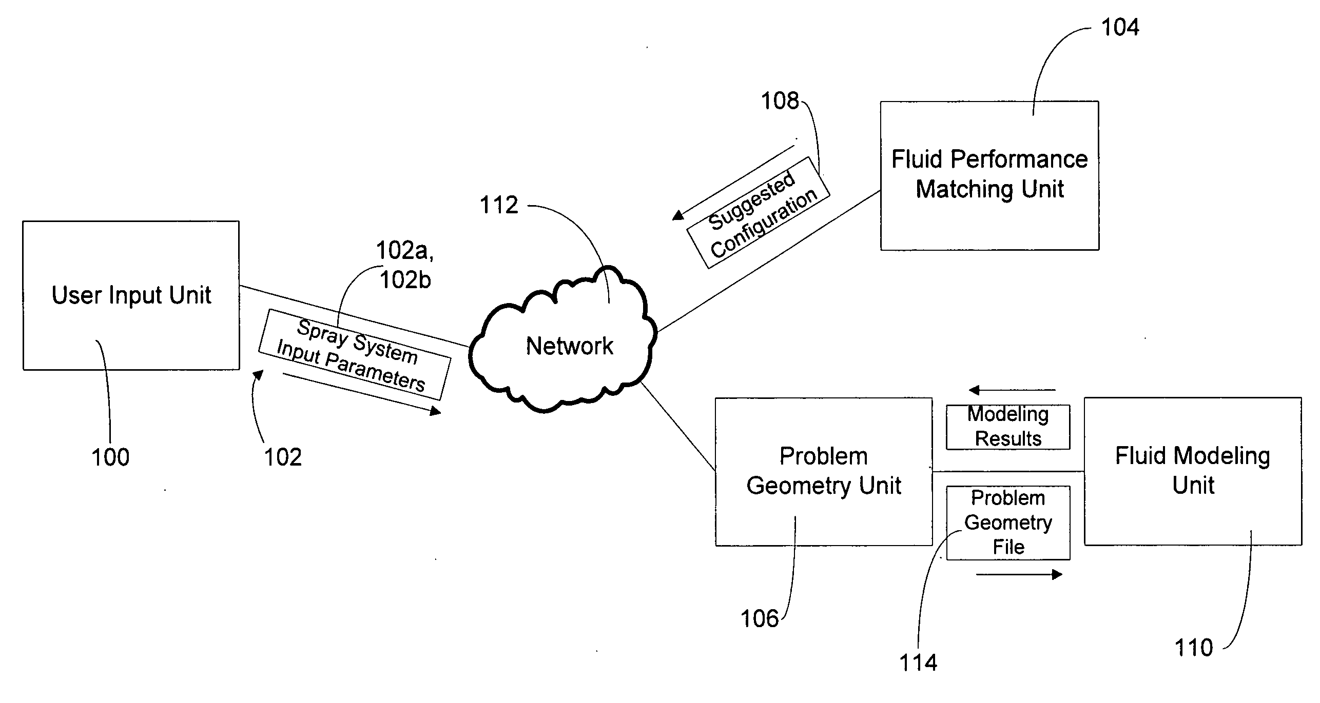
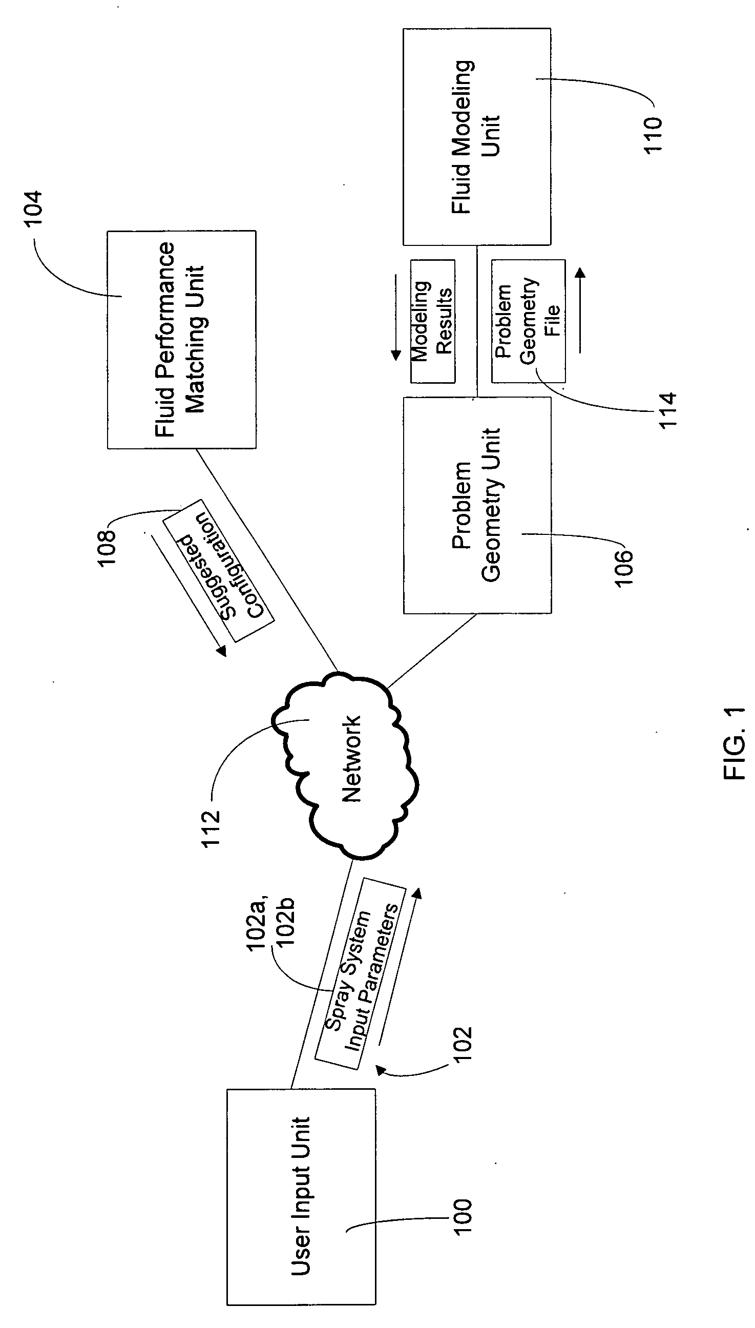
[0017]The following examples further illustrate the invention but are not intended to limit the scope of the attached claims. Turning to FIG. 1, an implementation of a system contemplated by an embodiment of the invention is shown with reference to spray injection analysis and nozzle configuration environment. To facilitate spray system configuration and spray nozzle selection, a user input unit 100 collects spray system input parameters 102 and relays the collected parameters to a fluid performance matching unit 104 and / or problem geometry unit 106 for subsequent processing. The user input module allows a user to input basic system parameters, including the desired spray fluid characteristics, to obtain suggested system configuration 108, including spray nozzle types and quantities, from the fluid performance matching unit 104.

[0018]Alternatively, when a user already knows the desired spray nozzle type and associated system parameters, the user input unit 100 may receive such infor...


PUM


Abstract

A spray injection analysis and nozzle configuration system is described having a user input unit that collects spray system input parameters and relays the collected parameters to a fluid performance matching unit and / or problem geometry unit for subsequent processing. The user inputs basic system parameters, including the desired spray fluid characteristics, to obtain suggested system configuration, including spray nozzle types and quantities. Accuracy of suggested spray nozzle type and configuration is increased via approximating the viscosity and / or surface tension parameters of the desired spray fluid with that of collected performance data. When a user already knows the desired spray nozzle type and associated system parameters, the user input unit routes this information to the problem geometry unit for creation of a problem geometry file, including calculation of the drop size distribution and spray velocity, and performance modeling via the fluid modeling unit.

Description

FIELD OF THE INVENTION[0001]This invention relates generally to the field of spray nozzle performance optimization and more specifically to the field of automated spray parameter and spray nozzle selection.BACKGROUND OF THE INVENTION[0002]Spray nozzle applications range from material coating to liquid cooling using various spray media and numerous nozzle configurations in order to match the specific needs of a given application. The broad spectrum of spray nozzle applications necessitates a careful analysis of spray injection parameters to come up with an optimum spray nozzle design, as well as to match an appropriate spray nozzle to a desired application.[0003]Flow modeling software applications, such as FLUENT, employ a Discrete Phase Model (DPM), which may be used for modeling of spray nozzle characteristics. However, such modeling software requires users to have the knowledge of complicated spray injection parameters to match the spray nozzle under analysis. Spray injection para...

Claims


Application Information

Patent Timeline
Patent Type & Authority Applications(United States)
IPC IPC(8): G06F17/10
CPCB05B12/00
Inventor SCHICK, RUDOLF J.CRONCE, KEITH L.KALATA, WOJCIECH
Owner SPRAYING SYST
Why Eureka
Try Eureka