
Molded insulated shoe footbed and method of making an insulated footbed

Active Publication Date: 2010-05-20
3M INNOVATIVE PROPERTIES CO
View PDF38 Cites 151 Cited by
  • Summary
  • Abstract
  • Description
  • Claims
  • Application Information

AI Technical Summary

Benefits of technology

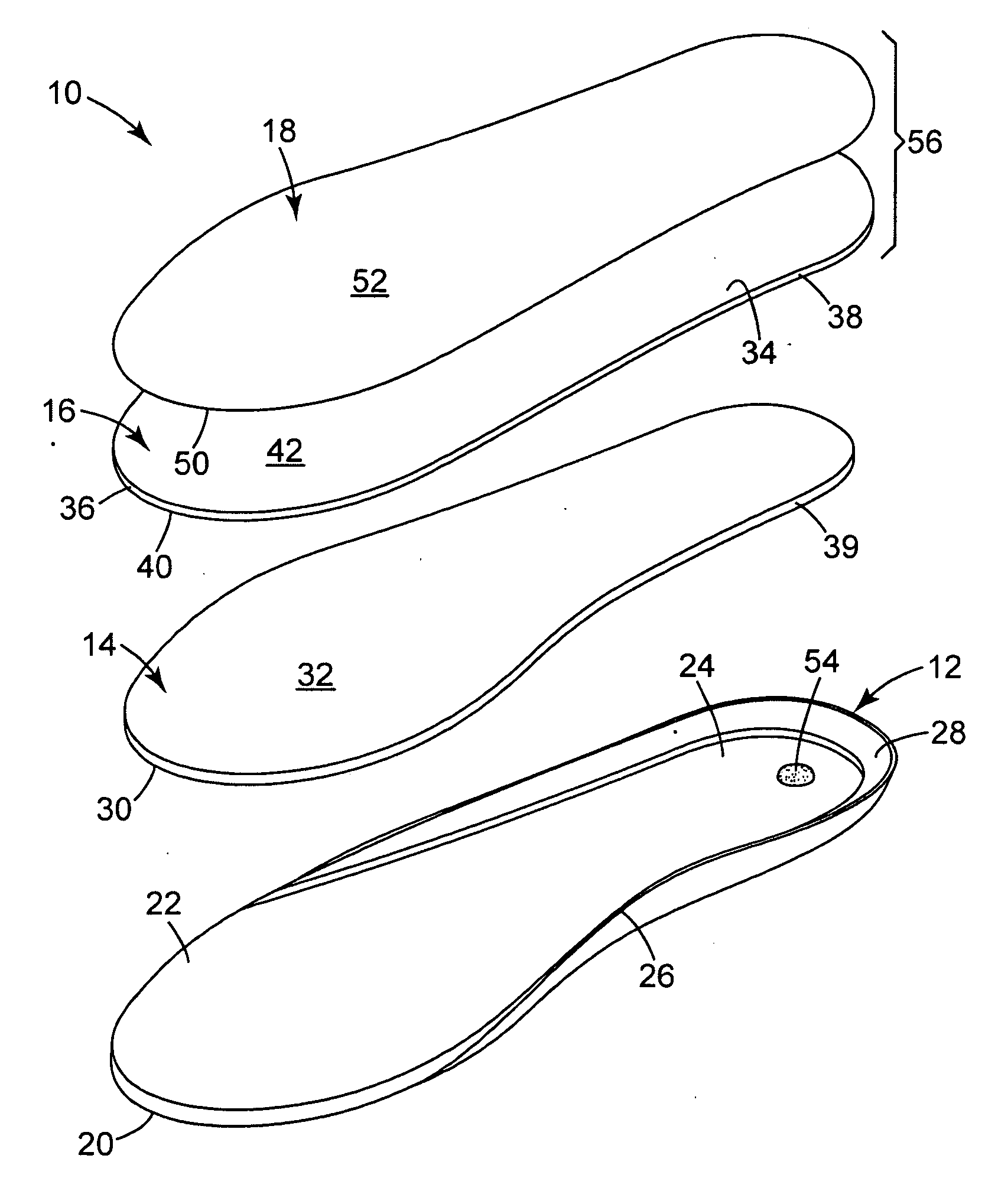
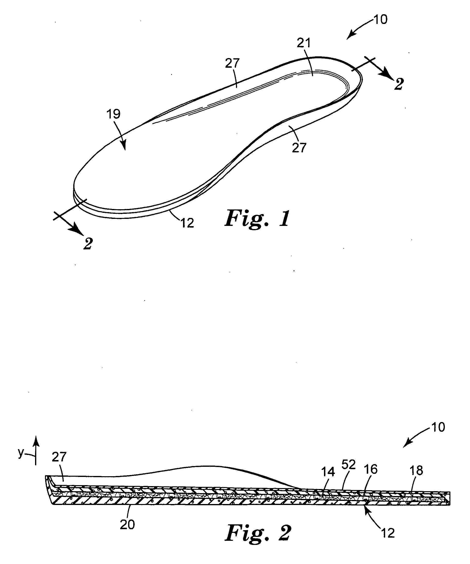
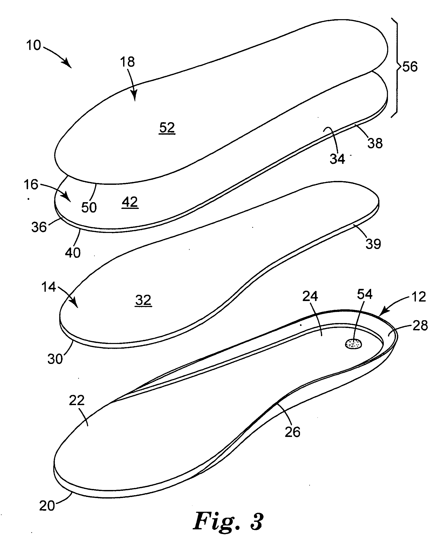
[0010]In the present invention, a shoe footbed is made by first molding a sheet material into a contoured shape-retaining layer. Following the molding step, a layer of thermal insulation is juxtaposed against the shape-retaining layer. One or more layers of a third material is positioned upon the layer of thermal insulation and optionally upon the top surface of the contoured shape-retaining layer. Because the shape-retaining layer is molded before the thermal insulation is placed on the second major surface of the shape-retaining layer, there is no risk for damaging the thermal insulation from exposure to heat during the molding step. Accordingly, the method of the present invention is particularly suited for enabling footbeds to be created which use non-woven webs that contain polymeric microfibers for the thermal insulation. Using the inventive method, shoe footbeds may be created that have lofty microfibrous insulation.GLOSSARY
[0017]“dab” means a small amount so as to not have a significant detrimental effect on overall permeability, insulation, or stiffness;

Problems solved by technology

Non-woven microfibrous webs, however, are sometimes subject to compression, which can reduce web loft and can cause a reduction in heat retention.
Shoe footbeds also have been developed which use a layer of thermal insulation to protect the wearer's feet from cold ambient temperatures (see, for example, U.S. Pat. No. 4,464,850 to Ebert et al. and U.S. Pat. No. 4,658,515 to Oatman) Known molded shoe footbeds, however, have not used thermal insulation that contains nonwoven webs of polymeric microfibers.
Processing articles that contain non-woven polymeric microfibrous webs can sometimes be problematic.
Because polymeric microfibers are subject to changes in morphology and structure when subjected to heat for only short time periods—and because some molding operations occur at temperatures at or above the melting temperature of the microfibers—the web and its heat retention capabilities may become damaged during subsequent molding operations.

Method used


Image

  • Molded insulated shoe footbed and method of making an insulated footbed
  • Molded insulated shoe footbed and method of making an insulated footbed
  • Molded insulated shoe footbed and method of making an insulated footbed

Examples


example 1

[0049]A pair of footbeds was constructed as follows. A thermoformable, open cell, polyurethane foam containing antimicrobial agent and red pigment was obtained from Kun Huang Enterprise Co, LTD in Taiwan under the trademarked Poliyou brand. The antimicrobial agent was Aegis Microbe Shield AEM 5772 available from Aegis Environments, Midland, Mich., USA. The foam was molded into the desired contoured shape. The thermoforming temperature was about 180 to 220° C., and the dwell was about 90 to 120 seconds. The forming was done in a steel mold. The resulting first surface of the foam took the decorative shape disclosed in design patent application Ser. No. 29 / 323,304 to Anderson et al. filed Aug. 22, 2008. The second surface of the foam had the shape shown in FIG. 3. The thickness of the shape-retaining layer was tapered from about 6 mm at the center of the heel-part to about 2 mm at the center of the fore-part. An adhesive dab was applied to the bottom of the heel cavity. The adhesive w...


PUM

PropertyMeasurementUnit
Temperatureaaaaaaaaaa
Lengthaaaaaaaaaa
Thicknessaaaaaaaaaa

Abstract

A shoe footbed 10 made by first molding a shape-retaining layer 12 into a contoured condition. After the shape-retaining layer 12 has been molded, a layer of thermal insulation 14 is placed on top of the molded layer 12. A conforming layer 16 and a fabric top layer 18 may be placed over the thermal insulation 14 and the shape-retaining layer 12. The inventive method of manufacture is particularly suited for making insulated footbeds that contain nonwoven webs of polymeric microfiber because damage to the fibrous web from heat and compression may be avoided.

Description

[0001]The present invention pertains to a shoe footbed that has a molded shape-retaining layer that has a contour molded into it and that contains polymeric microfibers.[0002]The present invention also pertains to a method of making a shoe footbed where the shape-retaining layer is first molded before having a layer of thermal insulation juxtaposed against it.BACKGROUND[0003]Thermal insulation that contains polymeric microfibers has been known for many years. This insulation is commonly used in jackets and sleeping bags to provide heat retention (see, for example, U.S. Pat. No. 5,565,154 to McGregor et al. and U.S. Pat. No. 4,933,129 to Hukman). Microfiber-containing insulation also has been used in shoes to assist in keeping a wearer's feet warm.[0004]Non-woven microfibrous webs, however, are sometimes subject to compression, which can reduce web loft and can cause a reduction in heat retention. In addressing this compression problem, investigators have corrugated nonwoven webs tha...

Claims


Application Information

Patent Timeline
IPC IPC(8): A43B7/06A43B13/38A43D8/00
CPCA43B17/14A43B17/003
Inventor PURRINGTON, SCOTT M.ROPPOLO, FRANK
Owner 3M INNOVATIVE PROPERTIES CO
Learn More