Cylindrical Tapered Thread Form for Tubular Connections

a tapered thread and tubular connection technology, applied in the direction of hose connection, rod connection, coupling, etc., can solve the problems of not being able to drive the well exactly vertically or even straight line, axial compressive load being exerted, and induced lower than desired stress and strain, so as to improve the design characteristics and performance

Active Publication Date: 2010-05-20
U S STEEL TUBULAR PROD
View PDF30 Cites 57 Cited by
  • Summary
  • Abstract
  • Description
  • Claims
  • Application Information

AI Technical Summary

Benefits of technology

[0019]The present invention has as its object to provide a further modification of the basic thread forms discussed above which provides impro

Problems solved by technology

Additionally, wells may not be driven in exactly vertical fashion or even in straight line fashion.
Sections of tubing or casing are sometimes driven into the well, resulting in axial compressive loads being exerted.
This trapped th

Method used


Image

  • Cylindrical Tapered Thread Form for Tubular Connections
  • Cylindrical Tapered Thread Form for Tubular Connections
  • Cylindrical Tapered Thread Form for Tubular Connections

Examples


Embodiment Construction

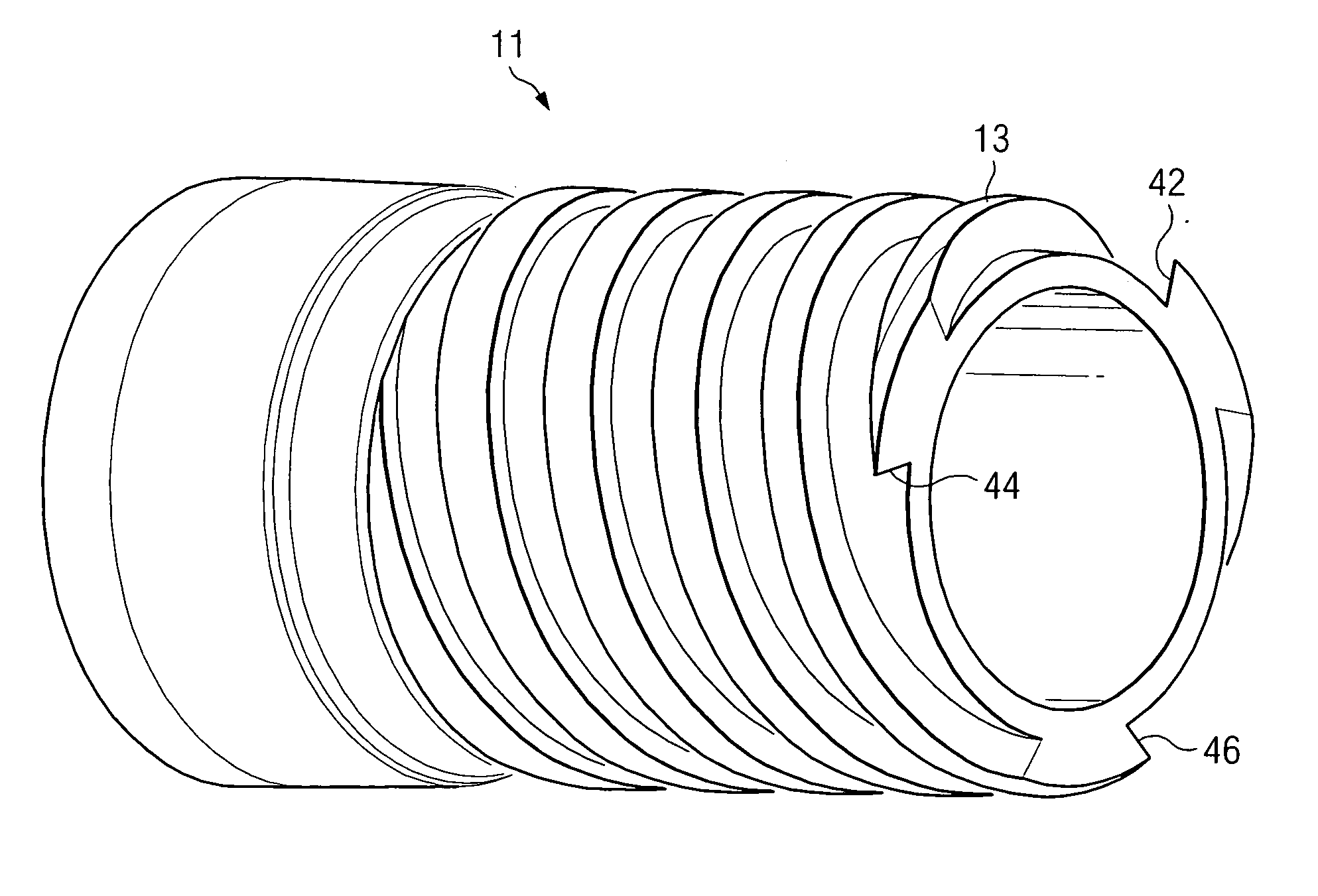
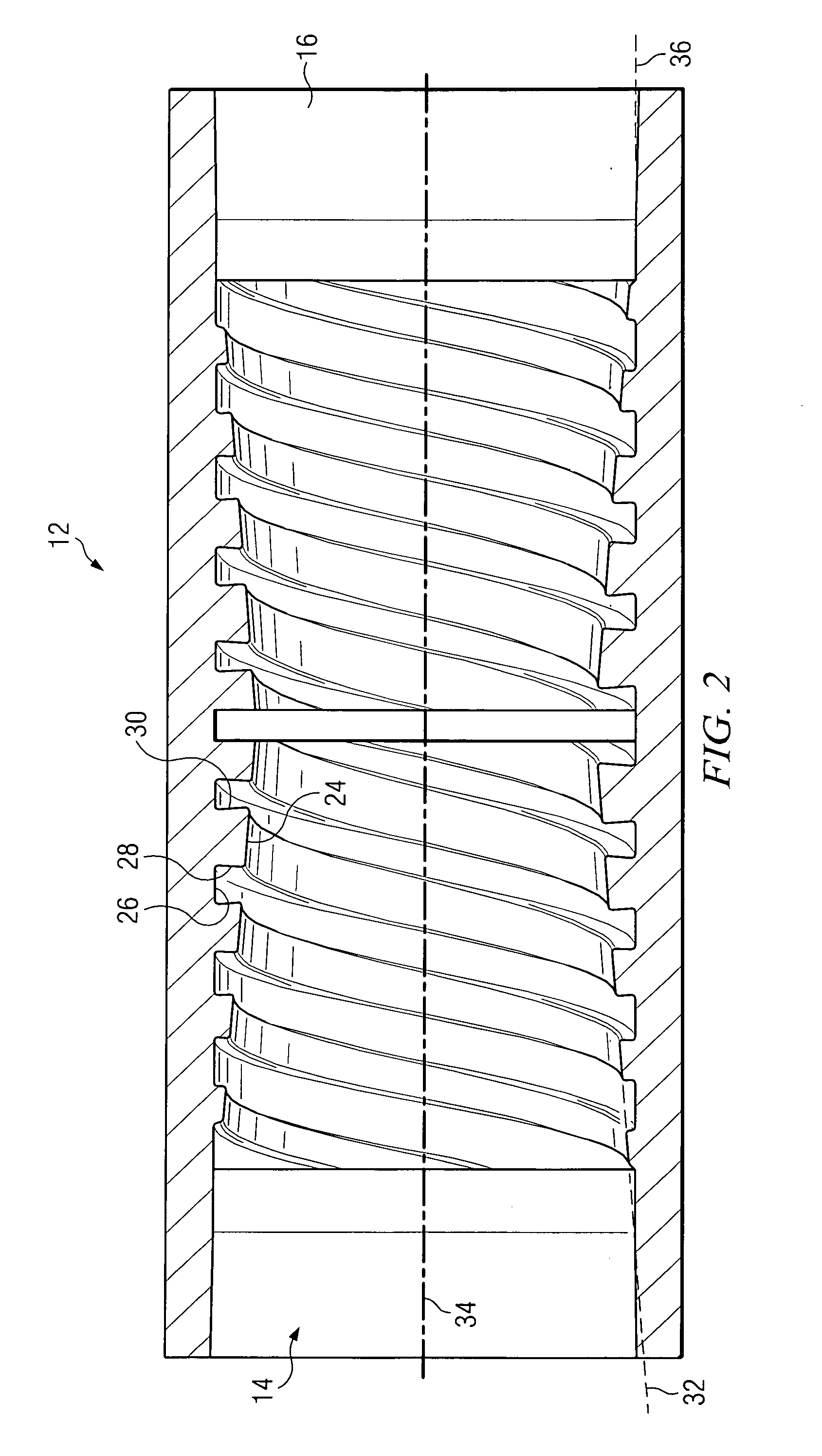
[0037]The invention described herein and the various features and advantageous details thereof are explained more fully with reference to the non-limiting examples which are illustrated in the accompanying drawing and detailed in the following description. Descriptions of well-known components and processes and manufacturing techniques are omitted so as to not unnecessarily obscure the workings of the invention. The examples used herein are intended merely to facilitate an understanding of ways in which the invention herein maybe practiced and to further enable those of skill in the art to practice the invention. Accordingly, the examples should not be construed as limiting the scope of the claimed invention.

[0038]For simplicity sake, the invention will be described in terms of a section of oil field drill pipe. It will be understood by those skilled in the relevant arts, however, that the thread form of the invention could be incorporated into a wide variety of threaded connections...


PUM


Abstract

A thread form is shown which is used to make a threaded connection between two tubular members and which is capable of being screwed together and subsequently unscrewed. A pin member is provided having external threads with stab flanks and load flanks and flat crests and roots for mating with the mating internal threads of a box member to make up a pipe connection. The thread crests on the pin member are cylindrical with respect to a central longitudinal axis of the tubular member while the thread roots are cut on a taper so that the height of the threads vary over the length of the thread form. The threads on the pin and box members can also be cut oppositely so that respective members of the thread forms are mirror images of each other.

Description

BACKGROUND OF THE INVENTION[0001]1. Field of the Invention[0002]The present invention relates to threaded tubular joints or connections and to a thread form for threaded connections of the type used for securing tubular flow conduits to form a desired continuous flow path.[0003]2. Description of the Prior Art[0004]A variety of threaded connections are known in the prior art for joining tubular flow conduits in an end-to-end relationship to form a continuous flow path for transporting fluid, gases or a combination of both. Typical examples of such flow conduits include casing, expandable casing, tubing, drill pipe and risers for oil, gas, water and waste disposal wells, and in horizontal and trenchless drilling applications. In the case of oil field casing and tubing, it is a common practice to use pipes of a definite length, with sections of pipe joined to form a string. The string of pipes effectively creates one lengthier pipe, intended to provide a means to reach the depth at whi...

Claims


Application Information

Patent Timeline
IPC IPC(8): F16L25/00F16D1/00
CPCF16L15/001Y10T403/635F16L15/006E21B17/042E21B17/0426F16B7/02
Inventor CHURCH, KRIS L.
Owner U S STEEL TUBULAR PROD
Why Eureka
Try Eureka