
Battery-Charging Device for a Stand-Alone Generator System having a MPPT Function and Method Thereof

a generator system and standalone technology, applied in battery overheating protection, secondary cell servicing/maintenance, safety/protection circuits, etc., can solve the problems of constant current charging method having a drawback of overcharge, damage to batteries, and shorten the life of batteries, so as to simplify the entire hardware circui

Active Publication Date: 2010-05-20
ABLEREX ELECTRONICS CO LTD
View PDF5 Cites 36 Cited by
  • Summary
  • Abstract
  • Description
  • Claims
  • Application Information

AI Technical Summary

Benefits of technology

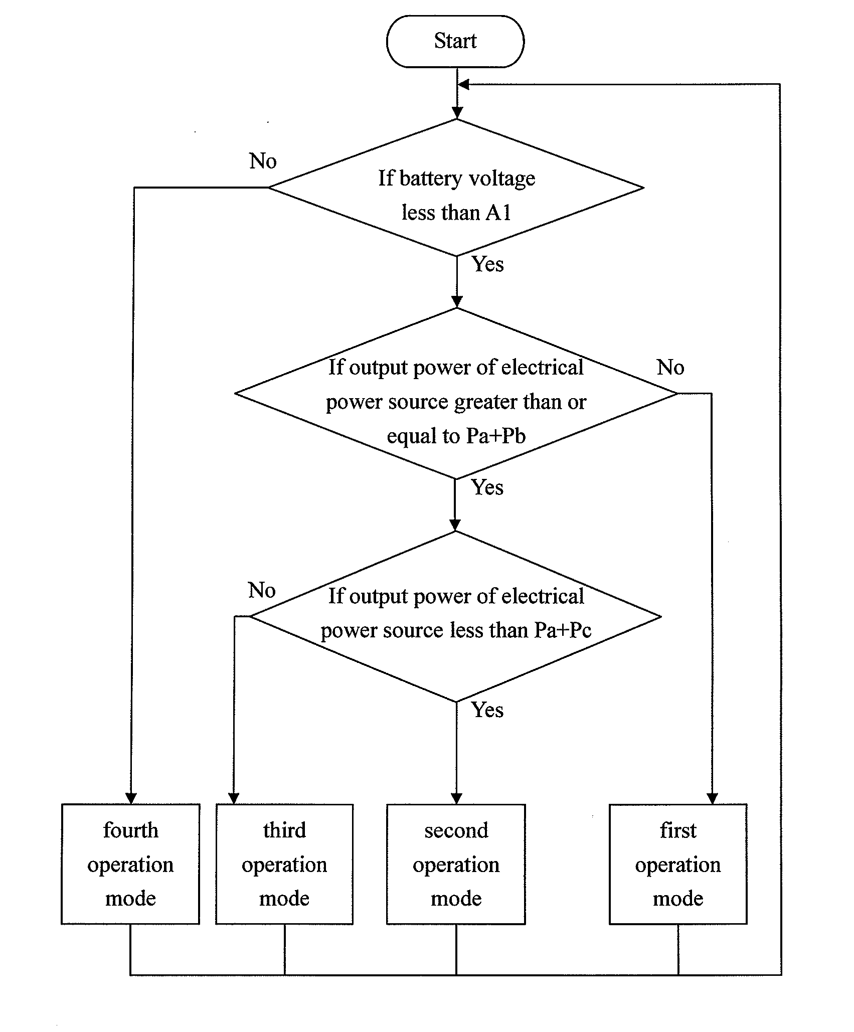
[0014]The primary objective of this invention is to provide a battery-charging device for a stand-alone generator system having a MPPT function. The battery-charging device includes a DC / DC converter and a control circuit. The control circuit is used to control the DC / DC converter performing four operation modes. The operation modes include a MPPT function, a pulse charging function, a constant voltage charging function and combinations thereof so as to simplify the entire structure of the hardware circuit and battery-charging modes.
[0016]Another objective of this invention is to provide the battery-charging method for a stand-alone generator system having a MPPT function. The battery-charging method provides four operation modes. When a generated output power of the electrical power source of the stand-alone generator system is low, the battery-charging device is operated with the MPPT function and provides a continuous charging current. If the generated output power of the electrical power source of the stand-alone generator system is lower than load power, the stand-alone generator system and the battery supply electric power to the load together. If the battery voltage is lower than a predetermined discharging voltage, the load is cut off. When the generated output power of the electrical power source of the stand-alone generator system is greater than the summation of the load power and the maximum charging power of the constant current charging method for the battery, the battery-charging device is switched and operated with a pulse charging method. In this manner, the battery-charging device is still controlled to execute the MPPT function if the generated output power of the electrical power source of the stand-alone generator system is not greater than the summation of the load power and a maximum charging power of the pulse charging method for the battery. The MPPT function is terminated if the generated output power of the electrical power source of the stand-alone generator system is greater than the summation of the load power and the maximum charging power of the pulse charging method for the battery. The battery-charging device is switched and operated as a constant voltage charging method so as to avoid overcharge if the battery voltage is greater than a predetermined constant charging voltage. Accordingly, the utilized generated output power of the electrical power source of the stand-alone generator system of the present invention can be effectively increased.
[0022]The battery-charging method of the present invention utilizes the DC / DC converter and the control circuit to select the MPPT function, the pulse charging function, the constant voltage charging function or combinations thereof so as to increase the utilized output power of the stand-alone generator system.

Problems solved by technology

A conventional small stand-alone wind energy or solar energy generator system means that the electric power generator system directly supplies to loads and redundant electric power will charge batteries for storing energy.
Disadvantageously, rapidly improper charging may cause damage to batteries and may shorten the life of battery.
For instance, the constant current charging method has a drawback of overcharge occurrence when the battery voltage is high.
In addition, the constant voltage charging method has a drawback of causing a large charging current, when the battery voltage is low, and thus damaging the battery.
But such a charging method require a longer charging time.
As to the pulse current charging method, the damages to battery may be relatively small.
In this circumstance the MPPT function of the generator system is terminated so that the electric power generator system cannot supply the maximum electric power and the redundant electric power cannot be effectively utilized.
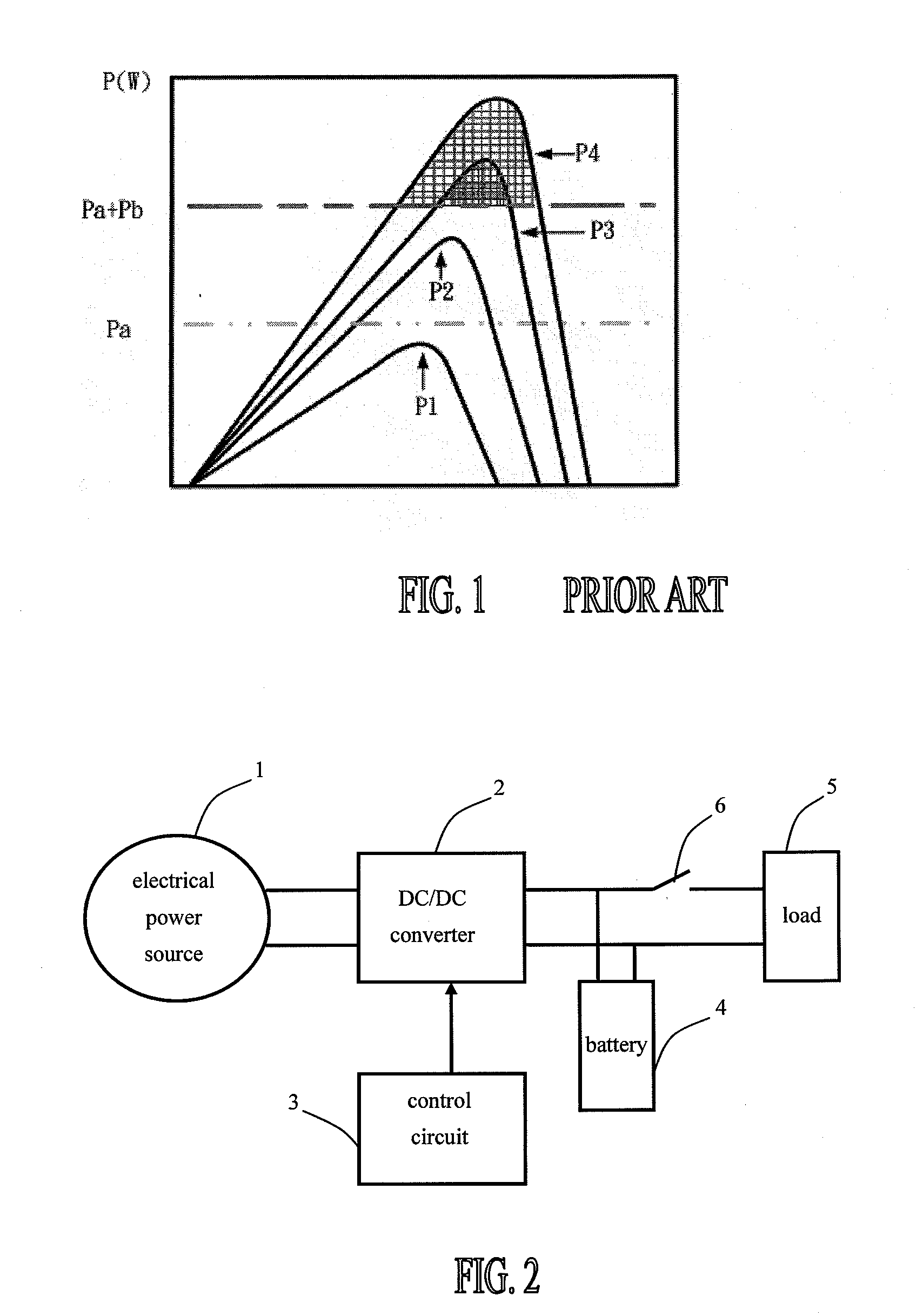
Disadvantageously, the output electric power generated by the electrical power source, as best shown in a meshed area in FIG. 1, cannot be effectively utilized while located in a maximum power area (i.e. redundant electric power area) of the curves P3 and P4.
However, the difference between the battery voltage and the output voltage of the battery-charging device is large when the battery is situated in low stored energy and it may cause an overcharging current if the battery-charging device is operated in a constant voltage charging mode.
Disadvantageously, the overcharging current may not only shorten the life of battery but also damage the battery-charging device.
Disadvantageously, the circuit hardware and the control method applied therein are complicated.

Method used


Image

  • Battery-Charging Device for a Stand-Alone Generator System having a MPPT Function and Method Thereof
  • Battery-Charging Device for a Stand-Alone Generator System having a MPPT Function and Method Thereof
  • Battery-Charging Device for a Stand-Alone Generator System having a MPPT Function and Method Thereof

Examples


Embodiment Construction

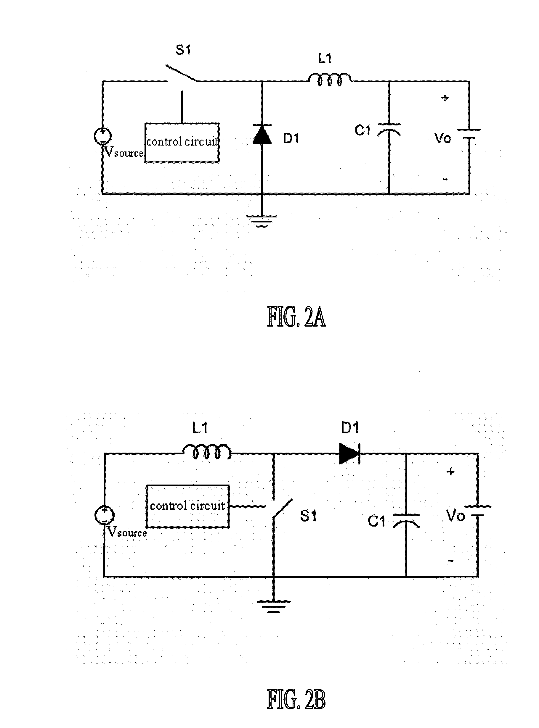
[0031]Throughout the specification, the terms “battery-charging device” and “battery-charging method,” as used herein, is applied to a stand-alone generator system having a MPPT function for using in electric power generated by wind energy, solar energy or other renewable energy which are not limitative of the present invention. The term “battery,” as used herein, will be understood to imply the inclusion of a battery unit or a battery set.

[0032]Referring now to FIG. 2, a battery-charging device for a stand-alone generator system having a MPPT function in accordance with the preferred embodiment of the present invention includes an electrical power source 1, a DC / DC converter 2, a control circuit 3, a battery 4 and a switch 6. The electrical power source 1 is used to supply a DC power, and is selected from a solar cell array or a wind power generator system provided with a rectified circuit. An input of the DC / DC converter 2 electrically connects with an output of the electrical pow...


PUM


Abstract

A battery-charging device, having a maximum power point tracking (MPPT) function, for a stand-alone generator system includes a DC / DC power converter and a control circuit used to control the DC / DC power converter. The method applied in the device includes: performing a MPPT function to supply a continuous current when electric power generated from the electrical power source of the stand-alone generator system is low; operating a pulse charging function and continuing the MPPT function when the electric power generated from the electrical power source of the stand-alone generator system is high and not greater than the summation of load power and a maximum charging power of the pulse charging method for the battery; terminating the MPPT function while the electric power is greater than the summation of load power and the maximum charging power of the pulse charging method for the battery; operating a constant-voltage charging mode when the battery voltage is greater than a predetermined constant charging voltage.

Description

BACKGROUND OF THE INVENTION[0001]1. Field of the Invention[0002]The present invention relates to a battery-charging device for a stand-alone generator system having a MPPT (maximum power point tracking) function and a method thereof. Particularly, the present invention relates to the battery-charging device and the method thereof applied to electrical generation equipment of wind energy, solar energy or other renewable energy, wherein the battery-charging device includes a DC / DC converter and a control circuit. More particularly, the present invention relates to the control circuit of the battery-charging device is provided with four operation modes, and one of which is selected and actuated by output of wind energy or solar energy power and the state-of-health of batteries so as to increase the utilization of wind energy and solar energy.[0003]2. Description of the Related Art[0004]A conventional small stand-alone wind energy or solar energy generator system means that the electric...

Claims


Application Information

Patent Timeline
Patent Type & Authority Applications(United States)
IPC IPC(8): H02J7/34
CPCH02J7/0008H02J7/0013H02J7/0014H02J7/0022H02J7/0031H02J2007/0098H02J7/0045H02J7/0091H02J7/027H02J2007/004H02J2007/005H02J7/0042H02J7/00041H02J7/00306H01M10/4257H02J7/0048H02J7/00047Y02E60/10H02J7/00302H02J7/00309H02J7/005H02J7/007194
Inventor WU, KUEN-DERTAI, HUNG-YUANLEE, JIE-TINWU, CHANG-CHUFENG, YA-TSUNG
Owner ABLEREX ELECTRONICS CO LTD
Learn More