
System for tracking vessels in automated laboratory analyzers by radio frequency identification

Active Publication Date: 2010-05-20
ABBOTT LAB INC
View PDF17 Cites 49 Cited by
  • Summary
  • Abstract
  • Description
  • Claims
  • Application Information

AI Technical Summary

Benefits of technology

[0020]The use of a radio frequency identification system allows a more compact physical architecture than would be possible with barcode technology by eliminating line of sight and spatial separation requirements, (b) improving reliability (in extreme environments) of reading information on a container, vessel, and microplate. The use of a radio frequency identification system also enables proper physical orientation of containers, i.e., the system ensures that a given container, vessel, microplate is in the proper location prior to its use.
[0021]Radio frequency identification can be used to increase the quantity of information on the container, the vessel, or the microplate. In addition, a radio frequency identification tag can be updated; a barcode cannot be updated. Furthermore, the information can be directly linked to a database, thereby providing (a) improved functioning of automated analyzer(s) in a system, (b) improved chain of custody, i.e., improved information relating to locations occupied by a given container in the present and at times previous to the present, and (c) improved safety to patients by ensuring accurate results of assays. This information includes information relating to the analyzer, the environment, i.e., the environments experienced during shipping, storage, and usage of the contents of the container.
[0022]The system also provides the ability to positively verify a sample or identify a reagent during aspiration or dispensing, thereby enabling an operator of the system to be given physical access to samples and reagents, except for those samples and reagents currently being aspirated or dispensed. Physical access to samples or reagents currently being aspirated or dispensed should be prohibited to the operator in order to ensure the safety of the operator.

Problems solved by technology

The power of the radio frequency identification reader is attenuated to a level such that the given antenna is required to be in close proximity to the radio frequency identification tag, whereby the amount of noise and interference from nearby radio frequency identification tags on other containers are insufficient to adversely affect the integrity of the data received by the given antenna connected to the radio frequency identification reader.

Method used


Image

  • System for tracking vessels in automated laboratory analyzers by radio frequency identification
  • System for tracking vessels in automated laboratory analyzers by radio frequency identification
  • System for tracking vessels in automated laboratory analyzers by radio frequency identification

Examples


Embodiment Construction

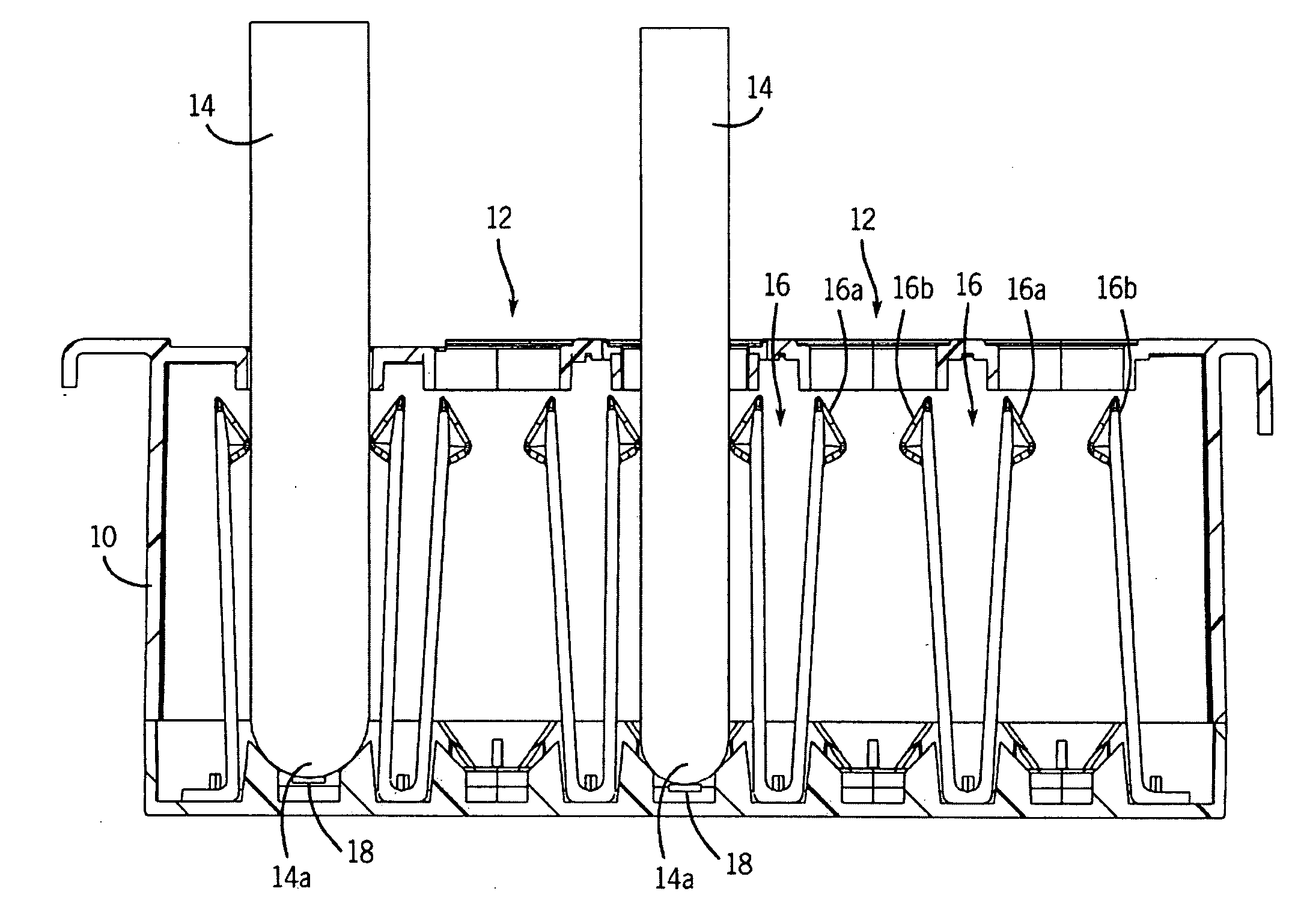
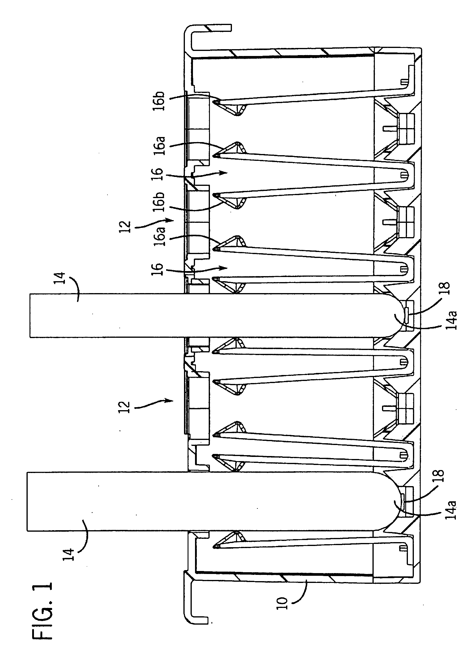
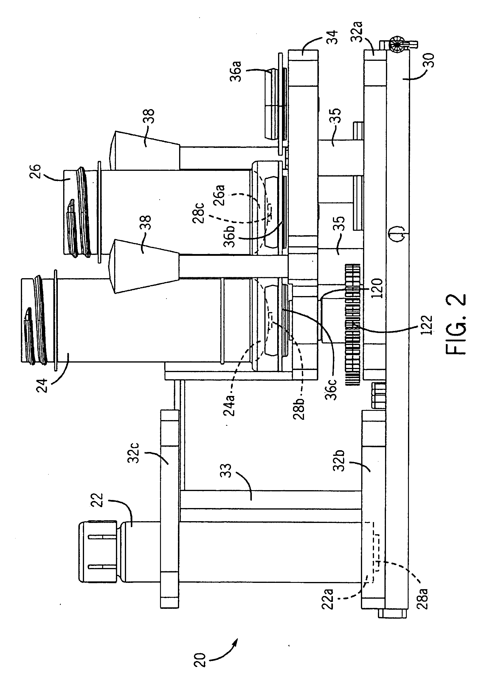
[0032]As used herein, the expression “radio frequency identification”, or “RFID”, is a generic term for technologies that use radio waves to automatically identify objects, such as, for example, containers for biological samples and containers for reagents for analyzing biological samples. The most common method of identification is to store a serial number that identifies the object, and perhaps other information relating to the object or contents thereof, on a microchip that is attached to an antenna. The microchip and the antenna together are called a radio frequency identification transponder or a radio frequency identification tag. The antenna enables the microchip to transmit the identification information and other information to an antenna connected to a radio frequency identification reader. The radio frequency identification reader converts the radio waves transmitted from the radio frequency identification tag into digital information that can then be passed on to compute...


PUM


Abstract

A system for automation of laboratory analyzers that utilizes radio frequency identification (RFID) tags and radio frequency identification (RFID) readers to identify containers and vessels, and the contents thereof, that are employed in the system. Radio frequency identification tags, conforming to the guidelines of ISO 18000 and either of ISO 14443 or ISO 15693, are positioned on the items of interest, such as, for example, reagent containers, sample containers, and microplates. These tags can be read by and written to by a stationary antenna connected to a radio frequency identification reader. Reading of radio frequency identification tags and writing to radio frequency identification tags are controlled by software.

Description

BACKGROUND OF THE INVENTION[0001]1. Field of the Invention[0002]This invention relates to systems that utilize automated laboratory analyzers, and more particularly, systems that utilize automated laboratory analyzers that require identification of containers for biological samples and reagents.[0003]2. Discussion of the Art[0004]Previous implementations for identification of reagents and other consumable items for automated laboratory analyzers have utilized barcode technology. Barcodes have been attached to items of interest, such as, for example, reagent containers, sample containers, e.g., test tubes, and test tube racks, and selectively scanned by a barcode reader for the purpose of identification and tracking of information associated with these items.[0005]Barcode technology has several limitations that inhibit optimally efficient architectures of automated analyzers for use in laboratories. Reading barcodes requires a direct line-of-sight from the barcode reader to the barco...

Claims


Application Information

Patent Timeline
IPC IPC(8): H04Q5/22
CPCG01N35/00732G16H10/40
Inventor FRITCHIE, PATRICK P.
Owner ABBOTT LAB INC
Learn More