Liquid crystal display panel and apparatus comprising the same

a technology of liquid crystal display panel and display panel, which is applied in the direction of instruments, non-linear optics, optics, etc., can solve the problems of increasing manufacturing cost and time, prone to defects, etc., and achieves the effects of preventing defects, reducing the use of shading tape, and improving backlight leakage problems

Inactive Publication Date: 2010-05-20
AU OPTRONICS (SUZHOU) CORP LTD +1
View PDF4 Cites 3 Cited by
  • Summary
  • Abstract
  • Description
  • Claims
  • Application Information

AI Technical Summary

Benefits of technology

[0007]Therefore, an aspect of the present invention is to provide a liquid crystal display panel and an apparatus comprising the same, thereby enlarging an area of a polarizer to reduce the use of the shading tape for improving the light leaking problem.
[0008]Another aspect of the present invention is to provide a liquid crystal display panel and an apparatus comprising the same, thereby preventing that the substrate of the display panel to directly contact with the supporting platform of the bonding tool when mounting an electric device, and thus preventing defects such as scratches or a fracture of the liquid crystal panel.
[0009]Another aspect of the present invention is to provide a liquid crystal display panel and an apparatus comprising the same, thereby reducing the peeling problem between a polarizer and a substrate.
[0010]Another aspect of the present invention is to provide a liquid crystal display panel and an apparatus comprising the same, thereby preventing that particles from a bonding area or other sources go into a backlight module of the apparatus.
[0014]Therefore, with the use of the liquid crystal display panel and the LCD apparatus disclosed in the embodiments of the present invention, the backlight leaking problem can be improved to reduce the use of the shading tape, and the panel of the invention can prevent that the substrate directly contacts with the supporting platform of the bonding tool when mounting the electric device, thereby preventing the defects such as scratches or the fracture of the liquid crystal panel and enhancing product yield and quality. Furthermore, the particles from a bonding area or other sources can be prevented from going into the backlight module of the LCD apparatus.

Problems solved by technology

However, the adhering process of the shading tape 926 needs labor effort and time, thereby increasing manufacturing cost and time.
At this time, if there is a particle between the supporting platform and the liquid crystal panel 920, it is susceptible to lead to defects such as scratches or a fracture of the liquid crystal panel 920.

Method used


Image

  • Liquid crystal display panel and apparatus comprising the same
  • Liquid crystal display panel and apparatus comprising the same
  • Liquid crystal display panel and apparatus comprising the same

Examples


first embodiment

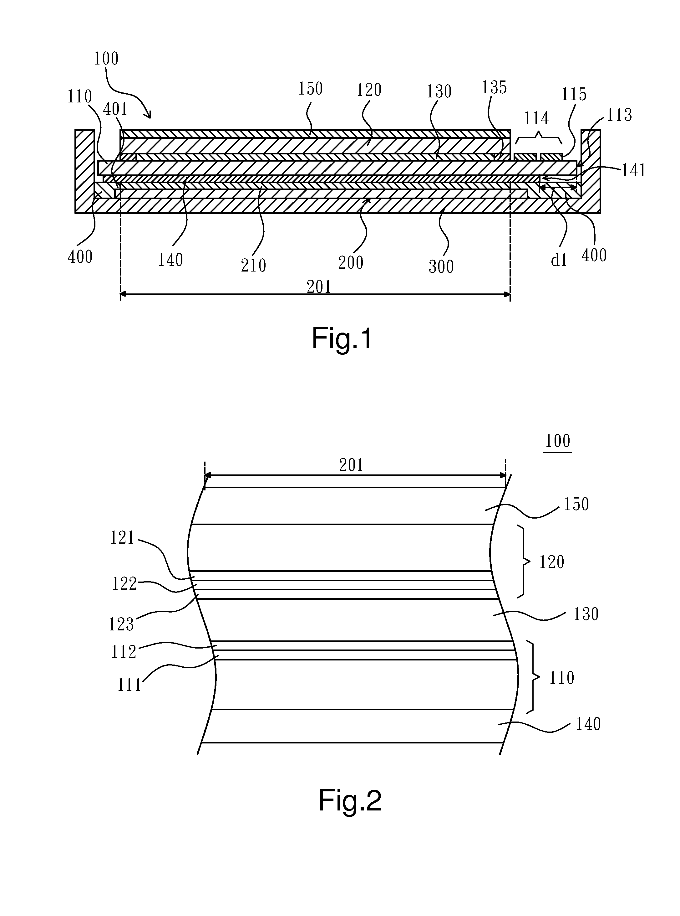
[0024]Referring to FIG. 1, a cross-section view showing a liquid crystal display panel and a backlight module according to the present invention is presented herein. The liquid crystal display panel 100 of the present invention is disposed opposite to a backlight module 200, thereby forming an LCD apparatus. The backlight module 200 may be an edge lighting backlight module or a bottom lighting backlight module, wherein the backlight module 200 may include an optical element assembly 210 for backlight efficiency and optical improvement. The optical element assembly 210 may include a diffuser, a light guide, a prism sheet, a turning prism sheet, a brightness enhancement film, a dual brightness enhancement film, a diffused reflective polarizer film or any combination thereof. The backlight module 200 may further include at least one light source (not shown), such as a cold cathode fluorescent lamp (CCFL), a hot cathode fluorescent lamp (HCFL), a light emitting diode (LED), an organic l...

second embodiment

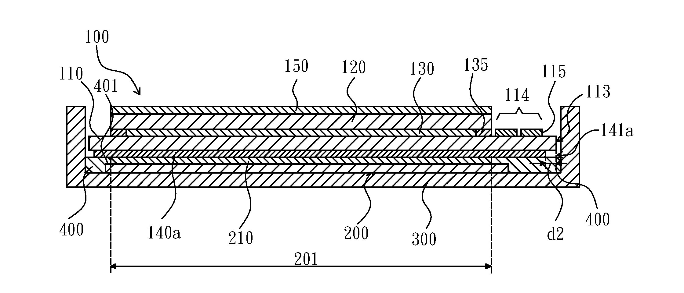
[0033]Referring to FIG. 4, a cross-section view showing a liquid crystal display panel according to the present invention is presented herein. The liquid crystal display panel 100 of the present embodiment comprises the first substrate 110, the second substrate 120, the liquid crystal layer 130, the first polarizer 140a and the second polarizer 150. The first substrate 110 has the first side face 113 and the bonding area 114, and the bonding area 114 is formed adjacent to the first side face 113 configured to mount at least one electric device 115 thereon. The liquid crystal layer 130 is disposed between the first substrate 110 and the second substrate 120 and sealed by dispensing a sealant 135. The first polarizer 140a is disposed at the outside of the first substrate 110 opposite to the liquid crystal layer 130, wherein the first polarizer 140a includes a second side face 141a. The second side face 141a and the first side face 113 are positioned at the same side of the liquid crys...


PUM

PropertyMeasurementUnit
distanceaaaaaaaaaa
distanceaaaaaaaaaa
distanceaaaaaaaaaa

Abstract

A liquid crystal display panel and an apparatus comprising the same are disclosed. The apparatus comprises the liquid crystal display panel and a backlight module. The backlight module includes a lighting area. The liquid crystal display panel is disposed opposite to the backlight module. The liquid crystal display panel comprises a first substrate facing the backlight module and a first polarizer disposed at the outside of the first substrate. The first polarizer covers the lighting area of the backlight module, but does not exceed or flush with the first substrate.

Description

CLAIM OF PRIORITY[0001]This application claims priority to Chinese Patent Application No. 200810202773.2 filed on Nov. 14, 2008.FIELD OF THE INVENTION[0002]The present invention relates to a liquid crystal display panel and an apparatus comprising the same, and more particularly, to a liquid crystal display panel and an apparatus comprising the same which can improve problems of light leaking and panel fracture.BACKGROUND OF THE INVENTION[0003]Liquid crystal displays (LCDs) have been widely applied in electrical products due to the rapid progress of optical and semiconductor technologies. With their advantages of high image quality, compact size, light weight, low driving voltage, low power consumption and various applications, LCDs have been introduced to be utilized in portable computers, mobile phones, personal digital assistants, and color televisions and are becoming the mainstream display apparatus.[0004]Referring to FIG. 7, a cross-section view showing a conventional liquid c...

Claims


Application Information

Patent Timeline
Patent Type & Authority Applications(United States)
IPC IPC(8): G02F1/13357G02F1/1335
CPCG02F1/133528G02F2001/133388G02F1/13452G02F1/133388
Inventor HAO, YAN-FEILEE, CHUN-YUHOU, SHUANG
Owner AU OPTRONICS (SUZHOU) CORP LTD
Why Eureka
Try Eureka