
Fluid catchment system for a wind turbine

a technology of wind turbines and catchments, applied in the direction of liquid fuel engine components, wind turbines, rigid containers, etc., can solve the problems of hydraulic system failure, hydraulic system failure, hydraulic system leakage, etc., and achieve the effect of preventing the burst of high-pressure fluid lines

Inactive Publication Date: 2010-05-20
FRONTIER PRO SERVICES
View PDF3 Cites 54 Cited by
  • Summary
  • Abstract
  • Description
  • Claims
  • Application Information

AI Technical Summary

Benefits of technology

[0015]In even a further embodiment, a fluid catchment system for a wind turbine blade is provided. The catchment system includes at least one fluid accumulator in fluid communication with an interior of the blade and configured to receive fluid moving from a root end of the blade towards a tip end of the blade. The fluid accumulator is configured to be positioned at least partially within the blade and to be attached to an interior surface of the blade. The fluid catchment system may further include an oil absorbent material, a seal configured to prevent leakage between the fluid accumulator and the surface of the blade, a lip configured to prevent fluid from exiting the catchment system in the direction of the root end of the blade, and an opening configured to allow the passage of fluid.
[0016]In another embodiment, a fluid catchment system for a wind turbine blade including a fluid accumulator in fluid communication with an exterior of the blade is provided. The fluid accumulator is configured to at least partially encircle the blade and to be attached to an exterior surface of the blade. The fluid catchment system may also include an oil absorbent material, a seal configured to prevent leakage between the fluid accumulator and the exterior surface of the blade, a lip configured to prevent fluid from exiting the catchment system in the direction of the root end of the blade, and / or an opening configured to allow the passage of fluid.

Problems solved by technology

Fluids can be spilled during commissioning or during normal maintenance of gearboxes and hydraulic systems.
Seals in gearboxes, cooling systems, and hydraulic systems can fail and leak.
High pressure fluid lines can burst.
This makes it very difficult to contain any leaking fluids, which simply fall out of the bottom of the nacelle, where they fall to the ground or run down the outside of the tower.
Spilled and leaked fluids can cause environmental, operational, and visual concerns.
Further, fluids on the towers can cause streaking and attract dirt.

Method used


Image

  • Fluid catchment system for a wind turbine
  • Fluid catchment system for a wind turbine
  • Fluid catchment system for a wind turbine

Examples


Embodiment Construction

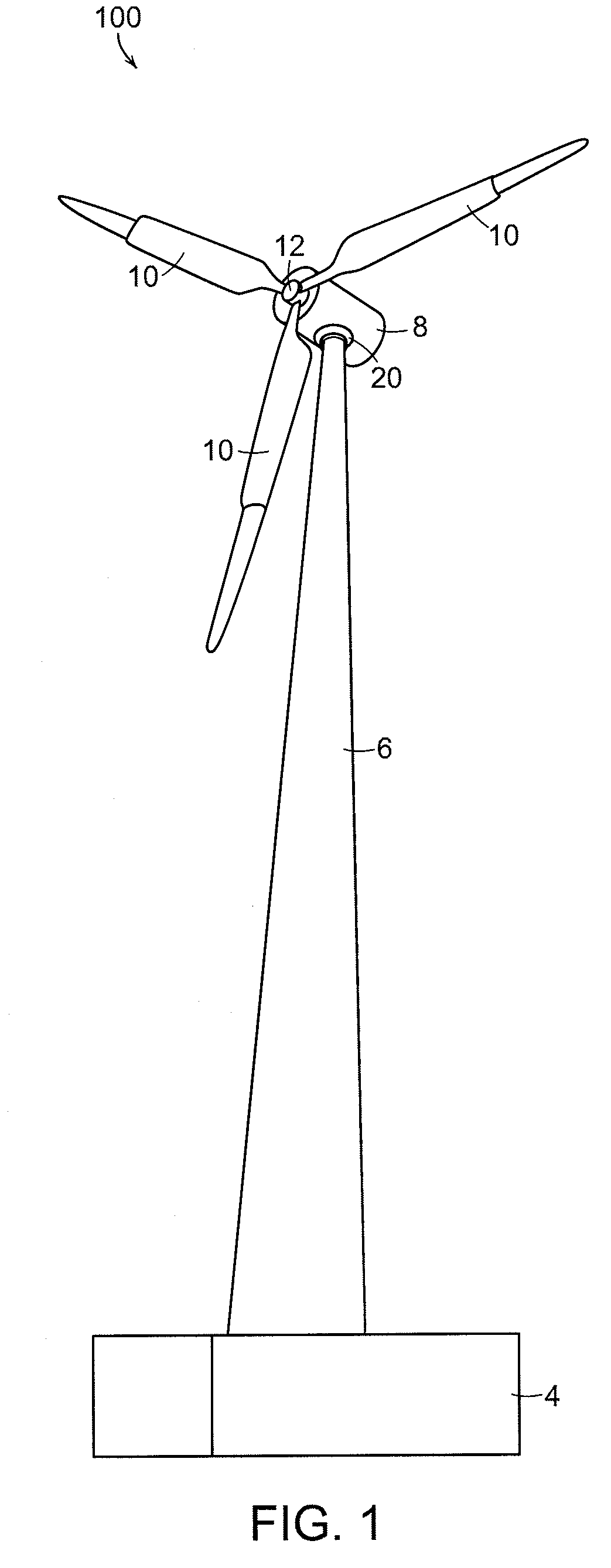
[0036]FIG. 1 shows a wind turbine 100 on a foundation 4 with a tower 6 supporting a nacelle 8. Multiple blades 10 are attached to a hub 12, each blade 10 having a root end and a tip end. Hub 12 is connected to a drive train within nacelle 8. A catchment system 20 is shown attached to tower 6 of wind turbine 100.

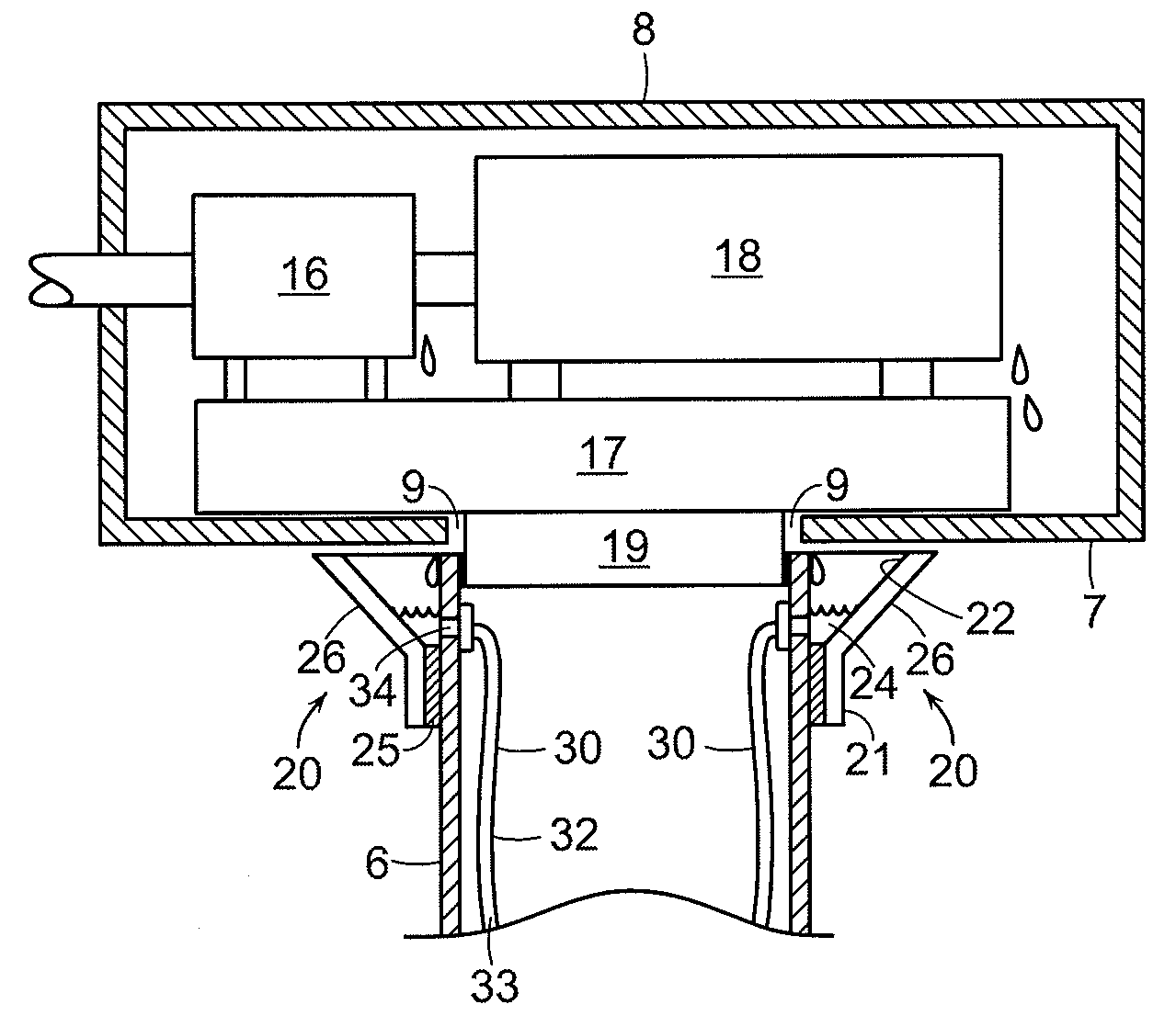
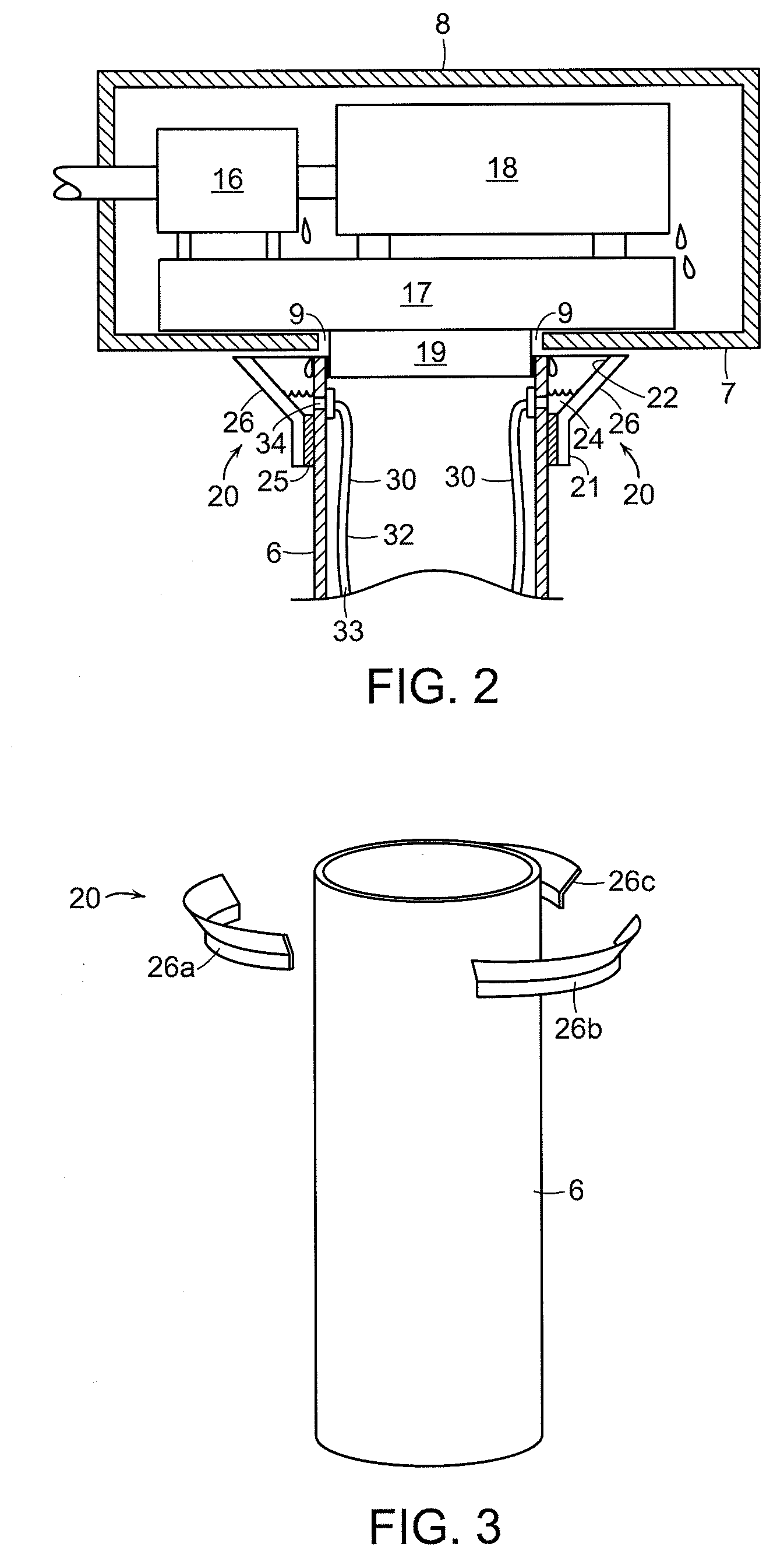
[0037]According to an embodiment of the present invention, FIG. 2 schematically illustrates an interior view of nacelle 8 and a cross-section of tower 6 used to support nacelle 8. Nacelle 8 typically houses, among other things, a gearbox 16 and a generator 18. Nacelle 8 is attached to tower 6 via a nacelle frame 17 and a bearing 19.

[0038]In the embodiment of FIG. 2, working fluids within nacelle 8 may exit (or leak) from nacelle 8 at a fluid egress region 9. Fluid egress region 9 is typically to be found where fluid leakage would most likely occur, i.e., at a lower surface 7 of nacelle 8. In one embodiment, fluid egress region 9 would most likely occur where nacelle 8 is moun...


PUM

PropertyMeasurementUnit
adhesiveaaaaaaaaaa
circumferential tensionaaaaaaaaaa
perimeteraaaaaaaaaa

Abstract

A fluid catchment system for a wind turbine is provided. The wind turbine has a nacelle mounted to a tower. The fluid catchment system includes at least one fluid accumulator in fluid communication with the interior of the nacelle and configured to receive fluid exiting from the nacelle. The fluid accumulator is configured to be positioned at least partially beneath the nacelle and to be attached to at least one of the tower and the nacelle. An oil absorbent material may be retained by the fluid accumulator. A fluid collector may be provided to collect fluid from the fluid accumulator. A fluid catchment system having a fluid accumulator located on a wind turbine blade is also provided. Further, a wind turbine including a fluid catchment system is provided.

Description

[0001]U.S. Provisional Application Ser. No. 60 / 831,263, filed January 2008, is hereby incorporated by reference in its entirety.FIELD OF THE INVENTION[0002]The invention relates to a fluid catchment system. Specifically, the invention relates to a fluid catchment system for use in the operation of tower-mounted wind turbines.BACKGROUND OF THE INVENTION[0003]A wind turbine is a machine that uses the kinetic energy of wind to generate electricity or to perform other useful work. Components in a wind turbine nacelle usually include a gearbox, generator, yaw drive, and blade pitch actuation system. Fluids used in turbines include, but are not limited to, coolant for cooling electronic and mechanical components, gear oil in gearboxes for lubrication and cooling, grease for lubricating bearings, and hydraulic fluid in actuation systems.[0004]There are a variety of ways in which these fluids can be spilled, leaked, etc. Fluids can be spilled during commissioning or during normal maintenanc...

Claims


Application Information

Patent Timeline
Patent Type & Authority Applications(United States)
IPC IPC(8): F03D11/00B65D1/34B23P11/00
CPCF03D11/0008F05B2260/98Y10T29/49963Y02E10/722Y02E10/726F16N31/004F05B2240/57F03D80/70Y02E10/72
Inventor WALLACE, JACKDAWSON, MARK
Owner FRONTIER PRO SERVICES
Features
  • Generate Ideas
  • Intellectual Property
  • Life Sciences
  • Materials
  • Tech Scout
  • Unparalleled Data Quality
  • Higher Quality Content
  • 60% Fewer Hallucinations
Learn More