Outboard Motor Mount

Inactive Publication Date: 2010-05-27
WAKEHAM LUKE ANDREW STUART
View PDF20 Cites 7 Cited by
  • Summary
  • Abstract
  • Description
  • Claims
  • Application Information

AI Technical Summary

Benefits of technology

[0038]a movement means to move at least a portion of the mounting plate relative to the supp

Problems solved by technology

However, there are also negative side effects.
However, the mounting bracket provided with boat motors typically has a very small rang

Method used


Image

  • Outboard Motor Mount
  • Outboard Motor Mount
  • Outboard Motor Mount

Examples


Embodiment Construction

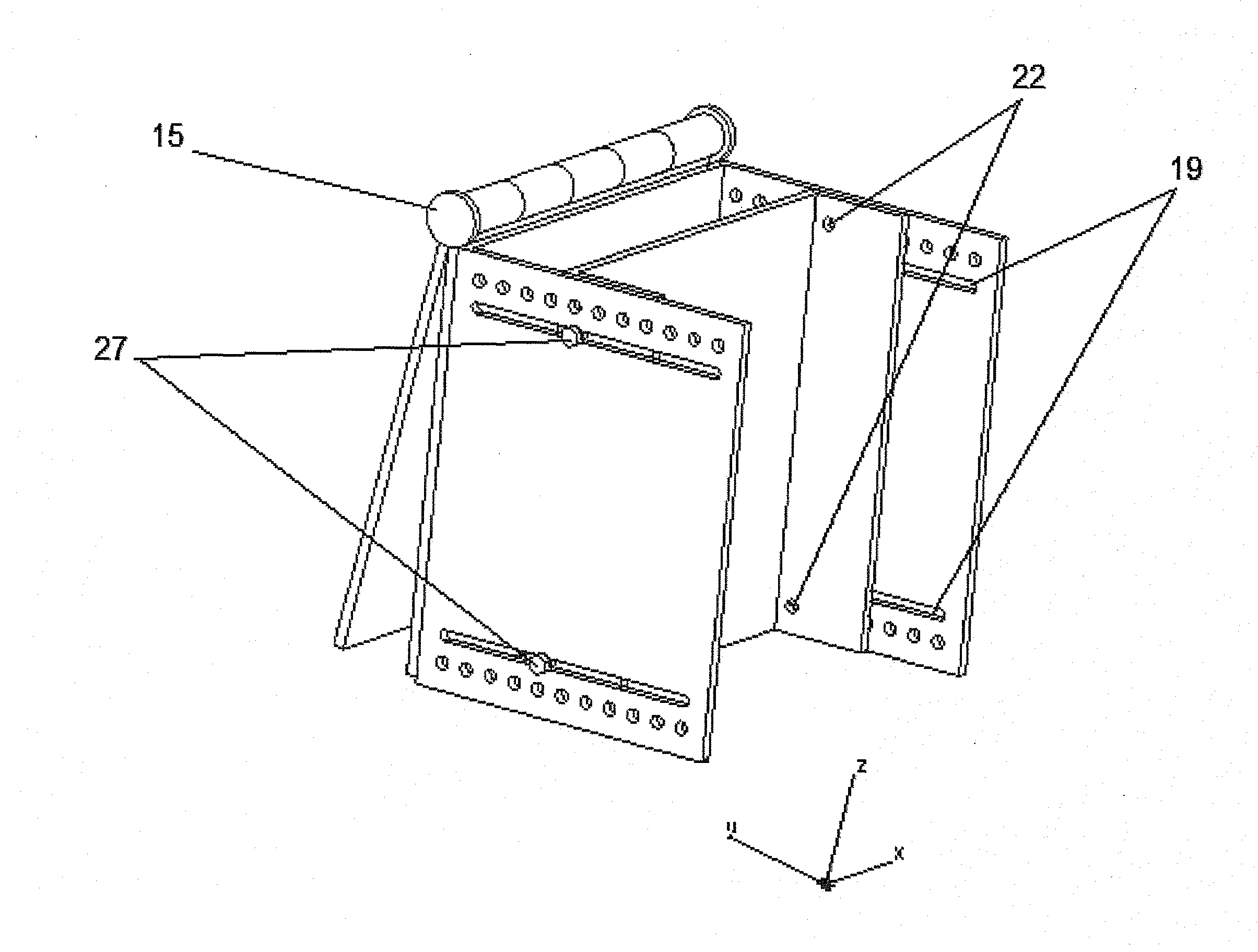
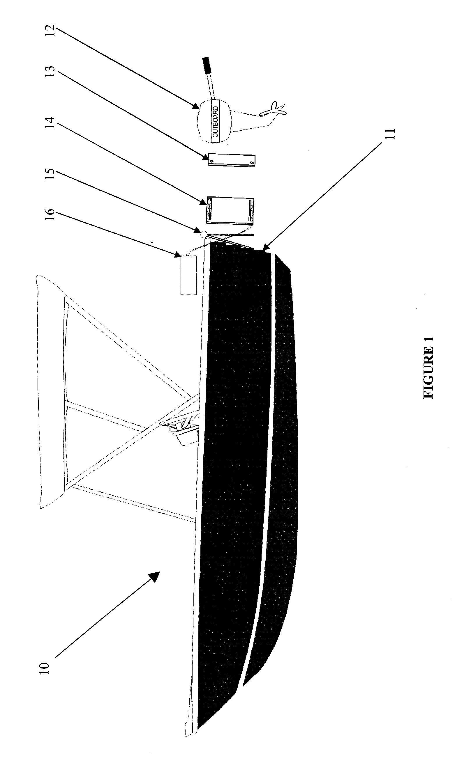
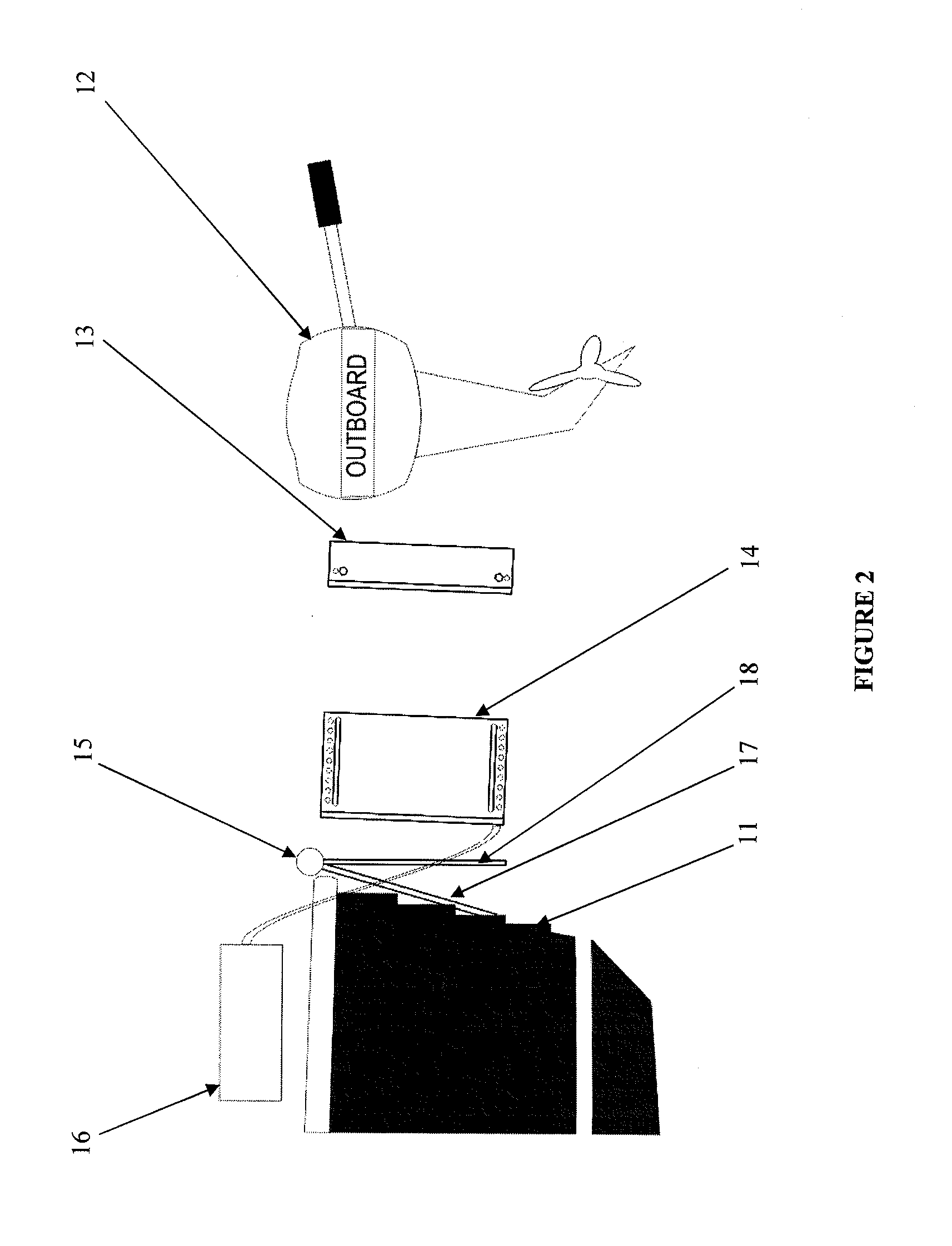
[0050]FIG. 1 illustrates a boat 10 having a transom 11 and an outboard motor 12. The outboard motor 12 would normally receive the transom 11 of the boat 10 into clamps (not shown). In an embodiment of the present invention, the outboard motor 12 instead clamps onto a mounting plate 13 which is received by a support structure 14. The support structure 14 is subsequently affixed to a pivot plate 15 that is affixed to the transom 11 of the boat 10. These components can be seen in more detail in FIG. 2.

[0051]An actuator 16 is provided that is preferably situated on the boat. The actuator 16 preferably assists movement of the mounting plate 13 with respect to the support structure 14 when they are engaged (i.e. as shown in FIGS. 3, 4, and 8 to 10). The pivot plate 15 comprises two plates hinged along one side (at point 15 in FIGS. 1 to 4). One plate 17 of the pivot plate 15 attaches to the transom 11 of the boat 10, and the second plate 18 is what the support structure 14 is attached to....


PUM


Abstract

The object of this invention is to alter speed and handling characteristics of an outboard motor boat. This Improved Outboard Motor Mount achieves this with the ability to adjust the distance between the outboard motor and the stern of the boat. Consequently, this movement uses the weight of the outboard motor as leverage to adjust the centre of gravity of the vessel to suit water conditions. Setting the outboard motor close to the stern of the boat will make the bow of the boat more difficult to lift, thus improving its handling performance in rough water. Setting the outboard away from the stern of the boat will make the bow of the boat easy to lift, improving boat speed. This Improved Outboard Motor Mount allows the consumer to optimize their outboard motor boats performance in a variety of water conditions.

Description

FIELD OF THE INVENTION[0001]This invention relates to outboard motor mounts for boats. More particularly, the invention relates to a maneuverable mount for outboard motors to be fitted to the transom of a boat.BACKGROUND ART[0002]Typically, outboard motors on water craft, such as a boat, are mounted onto a transom of the boat or an external transom bracket. It is known that placing the propeller of the motor at different distances and / or angles from the boat provides different handling, acceleration, and speed characteristics.[0003]The motor can be mounted rearward of the transom which provides some advantages. For instance, having the significant weight of the engine further back can assist in lifting the bow of the boat. This minimises the surface area of the boat on the water, maximising speed.[0004]Fuel efficiency is also improved as at a cruising speed a boat with less surface area needs less power to push it through the water. However, there are also negative side effects. Bec...

Claims


Application Information

Patent Timeline
IPC IPC(8): F16M7/00
CPCB63H20/10
Inventor WAKEHAM, LUKE ANDREW STUART
Owner WAKEHAM LUKE ANDREW STUART
Why Eureka
Try Eureka