Compact, interleaved radiation sources

a radiation source and interleave technology, applied in the field of compact, interleaved radiation sources, can solve the problems of large system size, large x-ray scanning system, large system size, etc., and achieve the effect of compact x-ray scanning system

Active Publication Date: 2010-05-27
VAREX IMAGING CORP
View PDF42 Cites 30 Cited by
  • Summary
  • Abstract
  • Description
  • Claims
  • Application Information

AI Technical Summary

Benefits of technology

[0008]Since the space occupied by an X-ray scanning system could often be used for o

Problems solved by technology

Such systems are generally large.
In addition, many such systems are too slow to economically inspect larger objects, such as cargo containers.
The length of the high energy X-ray sources and the beam arc tend to make higher

Method used


Image

  • Compact, interleaved radiation sources
  • Compact, interleaved radiation sources
  • Compact, interleaved radiation sources

Examples


Embodiment Construction

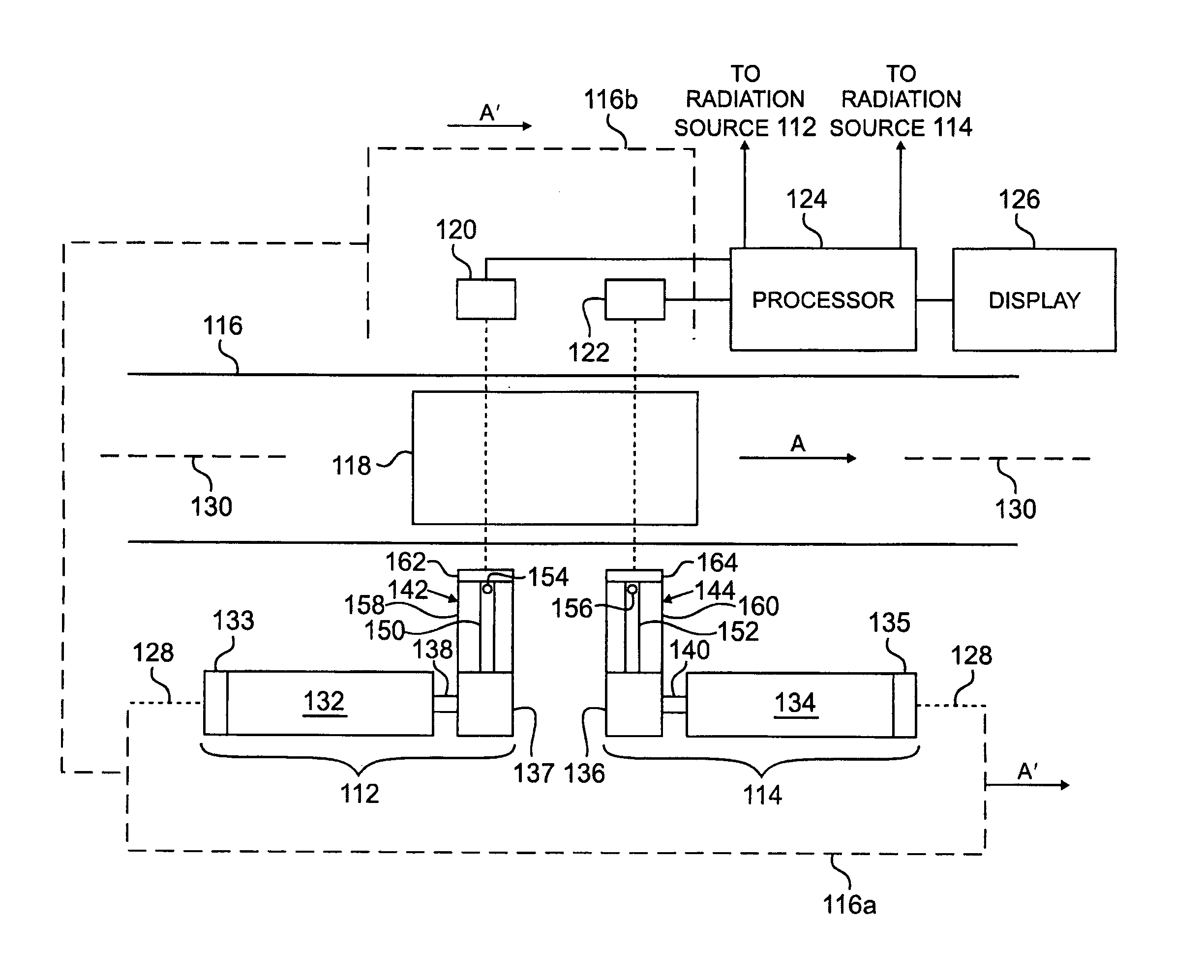
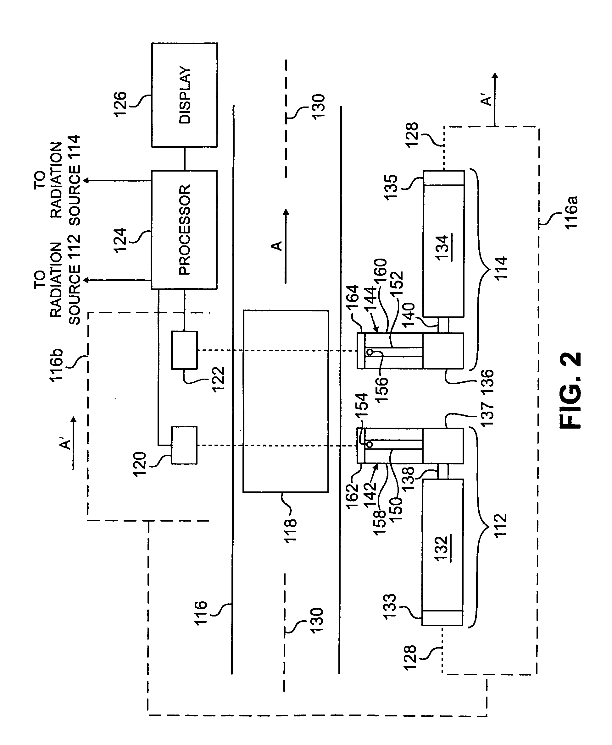
[0036]FIG. 2 is a schematic representation of a top view of a dual energy radiation scanning system 100 in accordance with an embodiment of the invention, comprising a first radiation source 112 and a second radiation source 114, adjacent to a support 116 for the object 118. In this example, the support 116 is a conveyor that moves the object 118, such as a cargo conveyance, in a direction A along an axis 130, past the radiation sources 112, 114. The conveyor 116 includes a flat surface 117 that supports the cargo conveyance 118. The radiation sources 112, 114 may be configured to generate fan beams or cone beams, for example, through which the object 118 is moved. Detectors 120, 122 are provided on an opposite side of the conveyor 116 than the radiation sources 112, 114. The detectors 120, 122 are aligned with the sources 112, 114, to detect radiation passing through the cargo conveyance 118. The detectors 120, 122 are coupled to a processor 124 and a display 126. The processor 124...


PUM


Abstract

Compact, dual energy radiation scanning systems are described comprising two particle beam accelerators, each configured to accelerate charged particles to different energies, positioned parallel to a direction of movement of an object to be inspected. The accelerator may be positioned perpendicular to a plane of the conveying system, instead. Bend magnet systems bend each charged particle beam toward a respective target. Alternatively, a single dual energy accelerator capable of accelerating charged particles to at least two different energies is positioned parallel to the direction of movement of the object, or perpendicular to a plane of the conveying system. A single bend magnet system is provided to bend each accelerated charged particle beam toward the same target. The particle beams may be bent through an orbit chamber. Two separate passages may be defined through at least part of the orbit chamber, one for charged particles having each energy.

Description

FIELD OF THE INVENTION[0001]Radiation sources and radiation scanning systems, and more particularly, X-ray radiation sources emitting radiation transverse to a longitudinal axis of the source and X-ray scanning systems using such sources for examining the contents of an object, for example.BACKGROUND OF THE INVENTION[0002]Radiation is commonly used in the non-invasive inspection of objects such as luggage, bags, briefcases, and the like, to identify hidden contraband at airports and public buildings. The contraband may include hidden guns, knives, explosive devices and illegal drugs, for example.[0003]FIG. 1 is a front view of an example of an X-ray scanning system 10, referred to as a line scanner, for scanning luggage in airports, for example. The object 12 to be inspected is conveyed through a shielded tunnel 13 between a stationary source of radiation 14, such as X-ray radiation, and a stationary detector array 16, by a conveying system 18. The source 14 is typically a source of...

Claims


Application Information

Patent Timeline
IPC IPC(8): G01N23/00H01J3/14G21K5/00
CPCG01V5/0041G21K1/093G01V5/0091H01J35/14G01N23/06G01N23/083H01J35/153
Inventor WHITTUM, DAVIDCLAYTON, JAMES E.
Owner VAREX IMAGING CORP
Why Eureka
Try Eureka