Electron beam control method, electron beam generating apparatus, apparatus using the same, and emitter

a technology of electron beam generating apparatus and control method, which is applied in the direction of beam deviation/focusing by electric/magnetic means, instruments, mass spectrometers, etc., can solve the problem of not being able to employ a field emitter in the practical sense of epma

Active Publication Date: 2010-05-27
SHIMADZU CORP +1
View PDF18 Cites 23 Cited by
  • Summary
  • Abstract
  • Description
  • Claims
  • Application Information

AI Technical Summary

Benefits of technology

[0016]The invention has been made in light of such circumstances and it is an object of the invention to provide an electron beam control method, an electron beam generating apparatus, capable of freely setting the angular current density in a Schottky emitter.

Problems solved by technology

Hence, it is impossible to employ a field emitter in instruments such as EPMA in a practical sense.

Method used


Image

  • Electron beam control method, electron beam generating apparatus, apparatus using the same, and emitter
  • Electron beam control method, electron beam generating apparatus, apparatus using the same, and emitter
  • Electron beam control method, electron beam generating apparatus, apparatus using the same, and emitter

Examples


Embodiment Construction

[0083]Detailed description will be given of a preferred embodiment of the invention below based on the accompanying drawings.

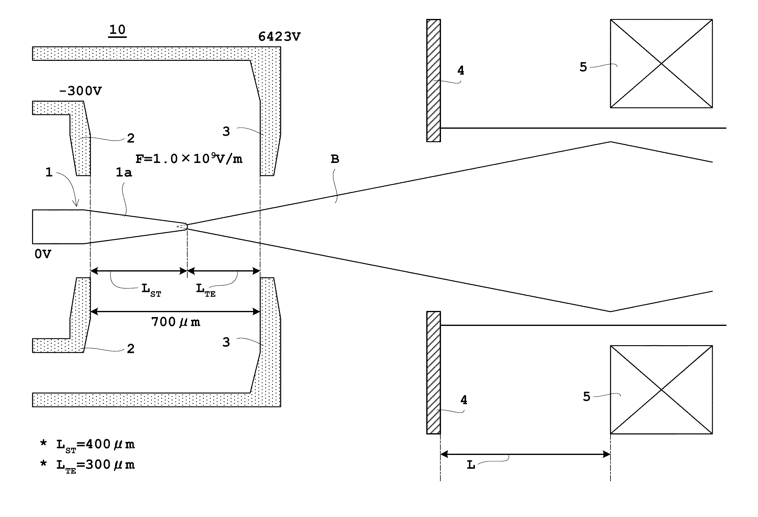
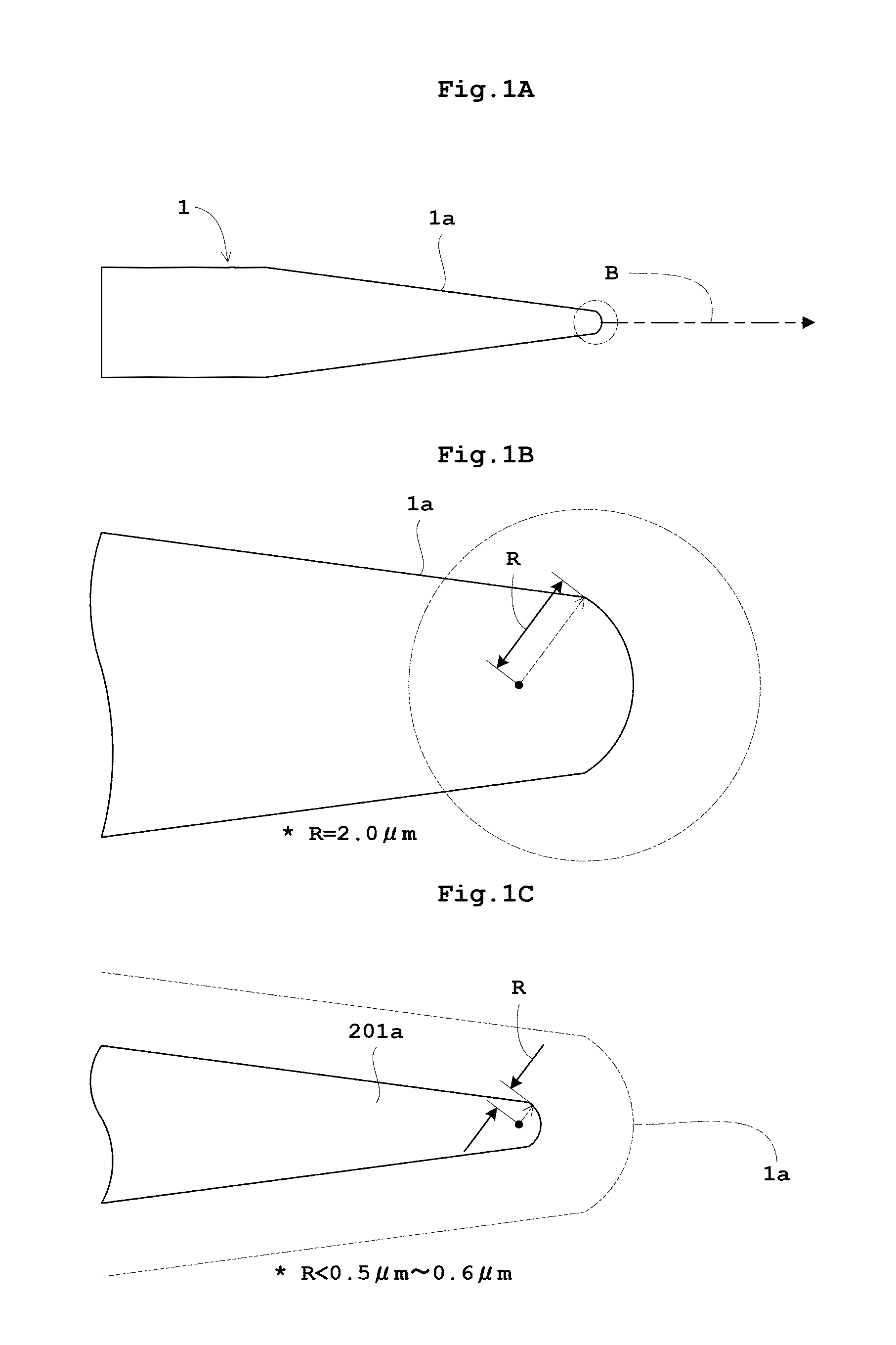
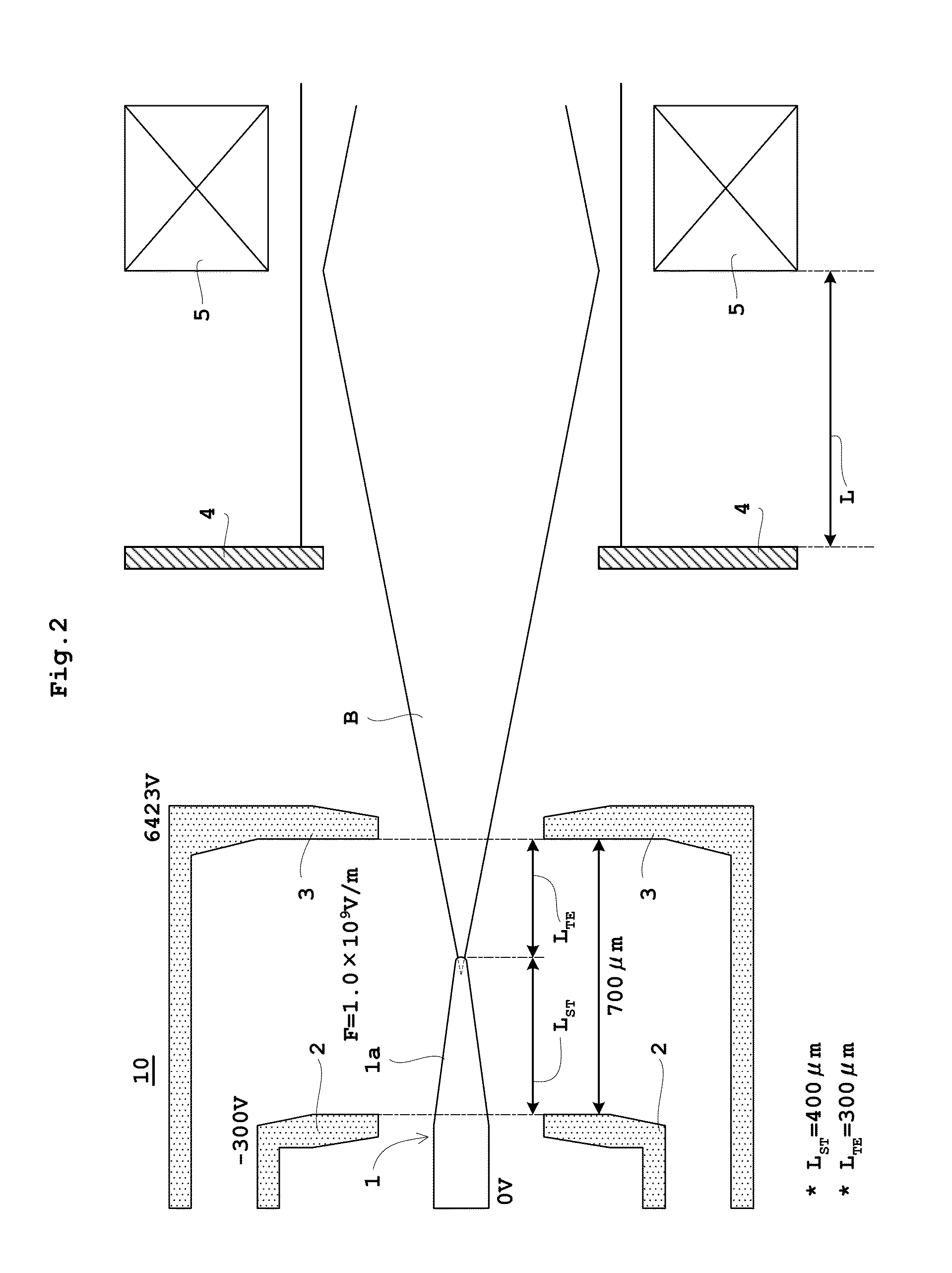
[0084]FIG. 1A is a schematic diagram showing a Schottky emitter related to one example of the invention. FIG. 1B is an enlarged schematic diagram of the conical end of the emitter. FIG. 1C is an enlarged diagram for comparison with the conical end of a conventional emitter. FIG. 2 is a schematic diagram of an electron beam generating apparatus equipped with the Schottky emitter. FIG. 3 is a schematic block diagram of an electron probe microanalyzer (EPMA) equipped with the electron beam generating apparatus.

[0085]A Schottky emitter 1 related to the example, as shown in FIG. 1A, has the conical end 1a sharpened in the shape of a cone on the emission side of an electron beam B (here, the symbol “B” in the figure denotes the electron beam and should not be confused with the quantity representing the brightness). The Schottky emitter 1 has a construction in which ...


PUM

PropertyMeasurementUnit
radiusaaaaaaaaaa
lengthaaaaaaaaaa
lengthaaaaaaaaaa

Abstract

Provided is a Schottky emitter having the conical end with a radius of curvature of 2.0 μm on the emission side of an electron beam. Since a radius of curvature is 1 μm or more, a focal length of an electron gun can be longer than in a conventional practice wherein a radius of curvature is in the range of from 0.5 μm to not more than 0.6 μm. The focal length was found to be roughly proportional to the radius of the curvature. Since the angular current intensity (the beam current per unit solid angle) is proportional to square of the electron gun focal length, the former can be improved by an order of magnitude within a practicable increase in the emitter radius. A higher angular current intensity means a larger beam current available from the electron gun and the invention enables the Schottky emitters to be used in applications which require relatively high beam current of microampere regime such as microfocus X-ray tube, electron probe micro-analyzer, and electron beam lithography system.

Description

BACKGROUND OF THE INVENTION[0001](1) Field of the Invention[0002]The invention relates to an electron beam control method, an electron beam generating apparatus, a device using the same, and an emitter.[0003](2) Description of the Related Art[0004]Electron guns in electron beam based instruments use two types of cathodes (emitters); a thermionic emitter and a field emitter. A thermionic emitter uses a tungsten filament, a pointed emitter of a single crystal or a sintered compound of lanthanium hexaboride (LaB6) or cerium hexaboride (CeB6). The emitter is heated and caused to emit thermal excited electrons to thereby generate an electron beam. A field emitter uses a sharpened conical end of an electrode on the emission side of an electron beam and emits electrons by using a tunneling effect or a Schottky effect caused by a strong electric field applied to the conical end to thereby generate an electron beam.[0005]Note that in a case where an analysis or observation is carried out in ...

Claims


Application Information

Patent Timeline
Patent Type & Authority Applications(United States)
IPC IPC(8): G01N23/225H01J29/46G21K1/08H01J35/06
CPCH01J35/06H01J37/065H01J2237/3175H01J2237/06316H01J2201/196H01J35/064
Inventor FUJITA, SHINEL-GOMATI, MOHAMEDWELLS, TORQUIL
Owner SHIMADZU CORP
Why Eureka
Try Eureka