Nuclear medical diagnostic device

a diagnostic device and nuclear technology, applied in the field of nuclear medical diagnostic devices, can solve the problems of adverse impact on image quality, inaccurate tomogram obtained by the pet device, medical diagnostic devices, etc., and achieve the effect of accurate assignment, high-quality tomogram and easy determination of optimal parameters

Inactive Publication Date: 2010-05-27
SHIMADZU CORP
View PDF1 Cites 2 Cited by
  • Summary
  • Abstract
  • Description
  • Claims
  • Application Information

AI Technical Summary

Benefits of technology

[0017]Through the above means, the optimal parameters may be decided. By using the optimal parameters, the position of a γ-ray source of the measurement object may be accurately assigned, so as to provide a high-qual...

Problems solved by technology

That is, the visual difference error becomes larger from the visual field centre to the peripheral parts, such that the tomogram obtained by the PET device becomes inaccurate.
However, the existing nuclear medical diagnostic device has the following problem.
Therefore, the optimal values of the parameters are not necessarily consistent, such that it is impossible ...

Method used


Image

  • Nuclear medical diagnostic device
  • Nuclear medical diagnostic device
  • Nuclear medical diagnostic device

Examples


first embodiment

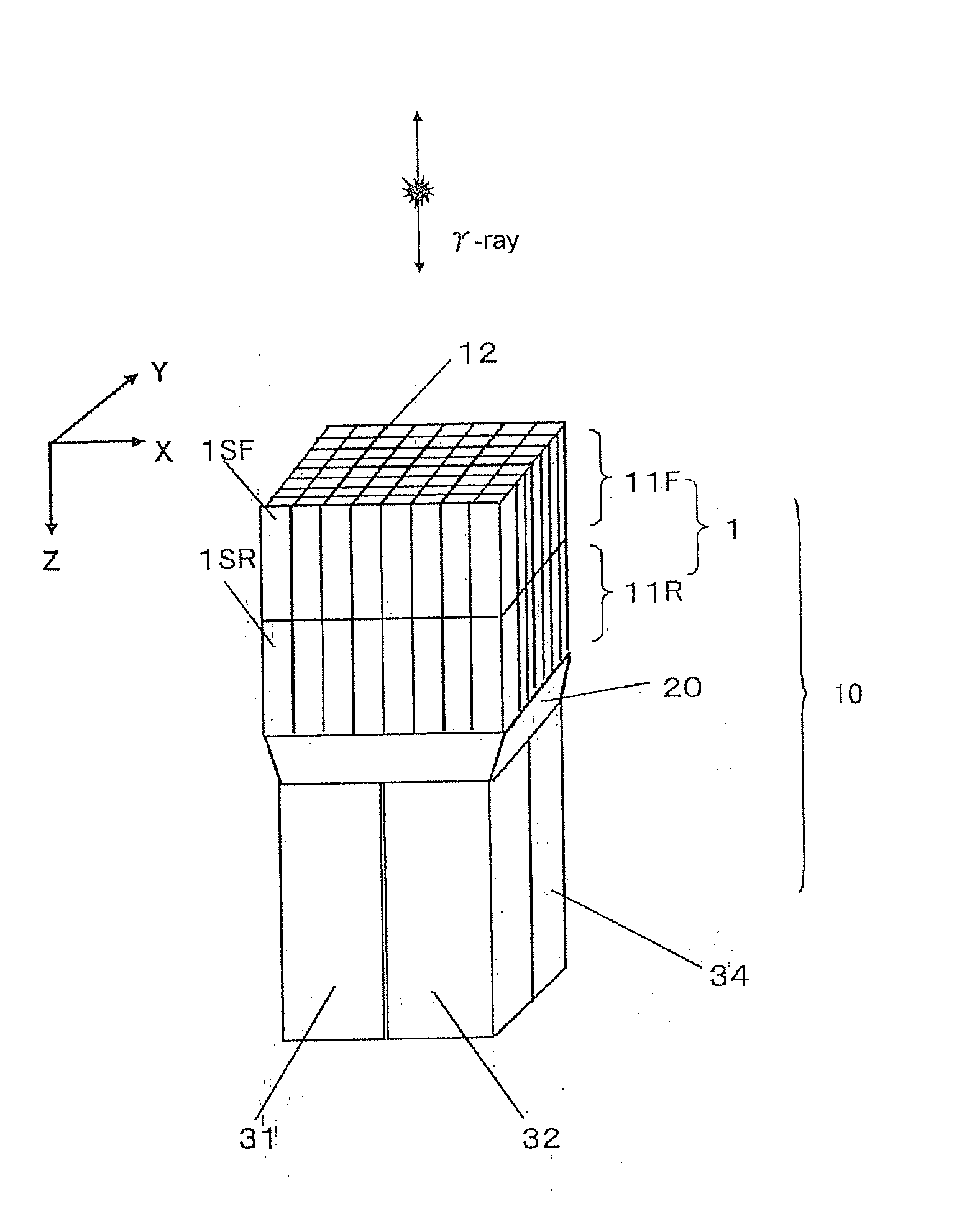
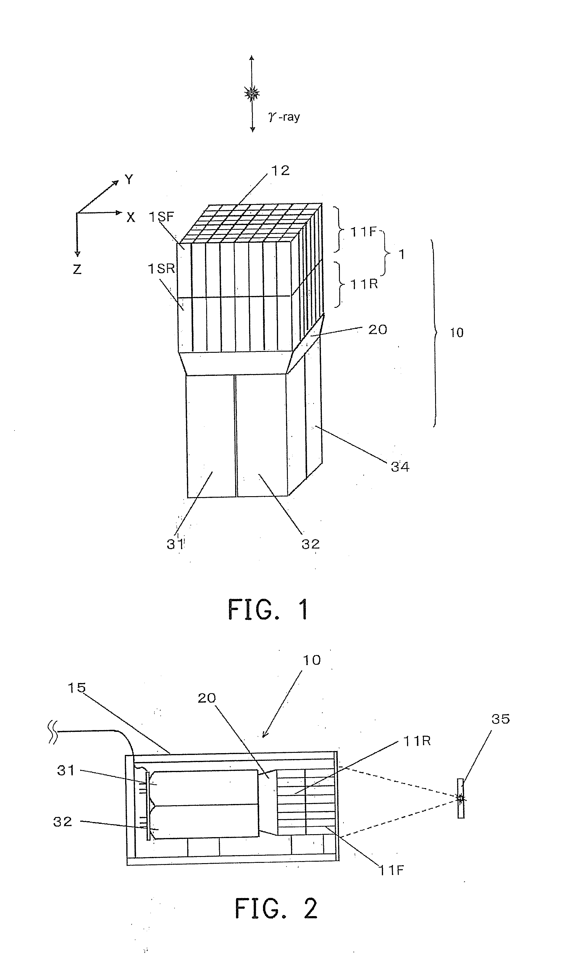
[0078]The detailed structure of a γ-ray detector according to the first embodiment of the present invention is shown in the drawings and is illustrated in the following. FIG. 1 is an outside view of a γ-ray detector 10 having scintillator arrays of a two-stage structure of the present invention. As shown in FIG. 1, in the γ-ray detector 10, a scintillator block 1 is arranged by being divided in a γ-ray incident depth direction, that is, the radiation detector 10 is a depth of interaction (DOI) γ-ray detector having three-dimensionally arranged scintillators. The DOI γ-ray detector of this embodiment has scintillator arrays of a two-stage structure.

[0079]The γ-ray detector 10 of this embodiment is approximately formed by four parts. The first part is a scintillator array 11F having scintillators 1SF that are two-dimensionally and compactly arranged and have a luminescence pulse with a shorter attenuation time. The scintillators 1SF are divided by appropriately sandwiching a light ref...

second embodiment

[0101]The detailed structure of the γ-ray detector according to the second embodiment of the present invention is shown in the drawings and is illustrated in the following. This embodiment is used for the situation in which the optimal values are more strictly decided. The scintillator array identification mechanism defines the first signal count ratio, which is R1=(N1−N1b) / (N2−N2b) and R1′=(N2′−N2b) / (N1′−N1b), obtained during the first inspection stage of the γ-ray detector single unit, and defines the parameters T1, T2, and K when the values of R and R′ are equal and become the maximum as the optimal values. Until now, the process is the same as that of the first embodiment (FIGS. 6 to 8).

[0102]As shown in FIG. 11, during a second inspection stage of the γ-ray detector single unit, the γ-ray detector 10 is disposed in the dark box 15, the optimal parameters T1, T2, and K decided above are input to the processing circuit for inspection 16. In this state, the Ri ray source 35 is arr...

third embodiment

[0110]The detailed structure of the γ-ray detector according to the third embodiment of the present invention is shown in the drawings and is illustrated in the following. The scintillator array identification mechanism defines the first signal count ratio, which is R1=(N1−N1b) / (N2−N2b) and R1′=(N2′−N2b) / (N1′−N1b), obtained during the first inspection stage of the γ-ray detector single unit, and defines the parameters T1, T2, and K when the values of R and R′ are equal and become the maximum as the optimal values. Until now, the process is the same as that of the first embodiment (FIGS. 6 to 8).

[0111]Then, as shown in FIG. 14, during a second inspection stage of the γ-ray detector single unit, the γ-ray detector 10 is disposed in the dark box 15, the optimal parameters T1, T2, and K decided above are input to the processing circuit for inspection 16. In this state, the Ri ray source 35 is arranged on a position at a distance 1 relative to the γ-ray detectors 10, and irradiates the γ...


PUM


Abstract

Parameters T1, T2, and K required by a scintillator array identification mechanism in a two-stage scintillator γ-ray detector (depth of interaction (DOI)) are accurately and easily determined. The parameters required by the scintillator array identification mechanism are determined with reference to a first signal count ratio, which is obtained by irradiating a γ-ray on each scintillator array with luminescence pulses in an incident depth direction of the γ-ray having different attenuation time during an inspection stage of the γ-ray detector single unit. Furthermore, a second signal count ratio is obtained by irradiating the γ-ray on a front surface of the γ-ray detector single unit, and then a third signal count ratio is obtained by irradiating the γ-ray on the front surface after the γ-ray detector single unit is installed in a PET device.

Description

BACKGROUND OF THE INVENTION[0001]1. Field of the Invention[0002]The present invention generally relates to a nuclear medical diagnostic device (an emission computed tomography (ECT) device), in which an radioactive agent is applied to a test subject, and a pair of γ-rays discharged by positron radioactive isotopes (RIs) accumulated in a target portion of the test subject is measured concurrently, so as to obtain a tomogram of the target portion. In particular, the present invention relates to a technique of counting γ-rays at the same time.[0003]2. Description of Related Art[0004]A positron emission tomography (PET) device is taken as an example to illustrate a nuclear medical diagnostic device, that is, an ECT device. The PET device is formed in the following manner. Opposite γ-ray detectors are used to detect two γ-rays at an angle of approximately 180° discharged from a target portion of a test subject. When the γ-rays are detected (counted) at the same time, a tomogram of the de...

Claims


Application Information

Patent Timeline
IPC IPC(8): G01T1/166G01T1/20
CPCG01T1/1648G01T1/1644
Inventor TONAMI, HIROMICHIOHI, JUNICHI
Owner SHIMADZU CORP
Why Eureka
Try Eureka