Inductance part
- Summary
- Abstract
- Description
- Claims
- Application Information
AI Technical Summary
Benefits of technology
Problems solved by technology
Method used
Image
Examples
first embodiment
(Second Modification of First Embodiment)
[0048]FIG. 5 illustrates a second modification in which the spacer is divided into a plurality of circular columns. As in the case of the first modification, a spacer 52 corresponding to the spacer 5 of the first modification is provided on the outer peripheral side of the winding 2. While the spacer 52 of the first modification has a ring shape, the spacer 52 of the second modification is constituted by a plurality of columnar-shaped spacers 53-1 to 53-4.
[0049]FIG. 6 illustrates an assembly state of the coil according to the second modification. As illustrated in FIG. 6, the spacers 53-1 to 53-4 are previously bonded to predetermined positions on the upper surface of the sheet coil 12. Further, the winding 2 formed by winding the triple insulated wire in a spiral manner is prepared. Then, the prepared winding 2 is fitted to a winding placement area which has been defined on the upper surface of the sheet coil 12 by the spacers 53-1 to 53-4 f...
second embodiment
[0051]FIG. 7 is a cross-sectional view partly illustrating a winding structure of a transformer 50 according to a second embodiment of the present invention.
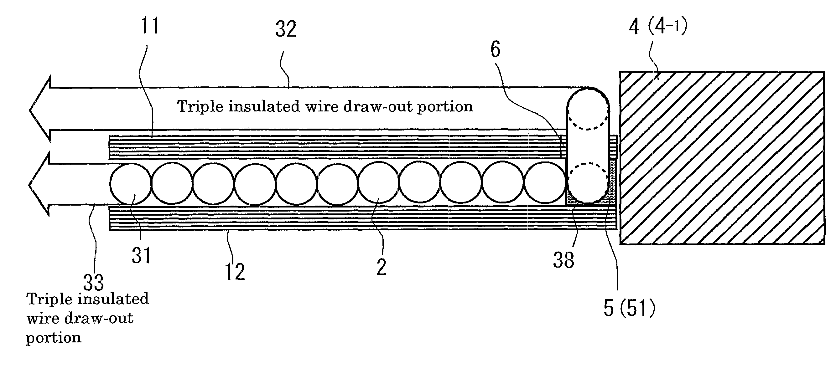
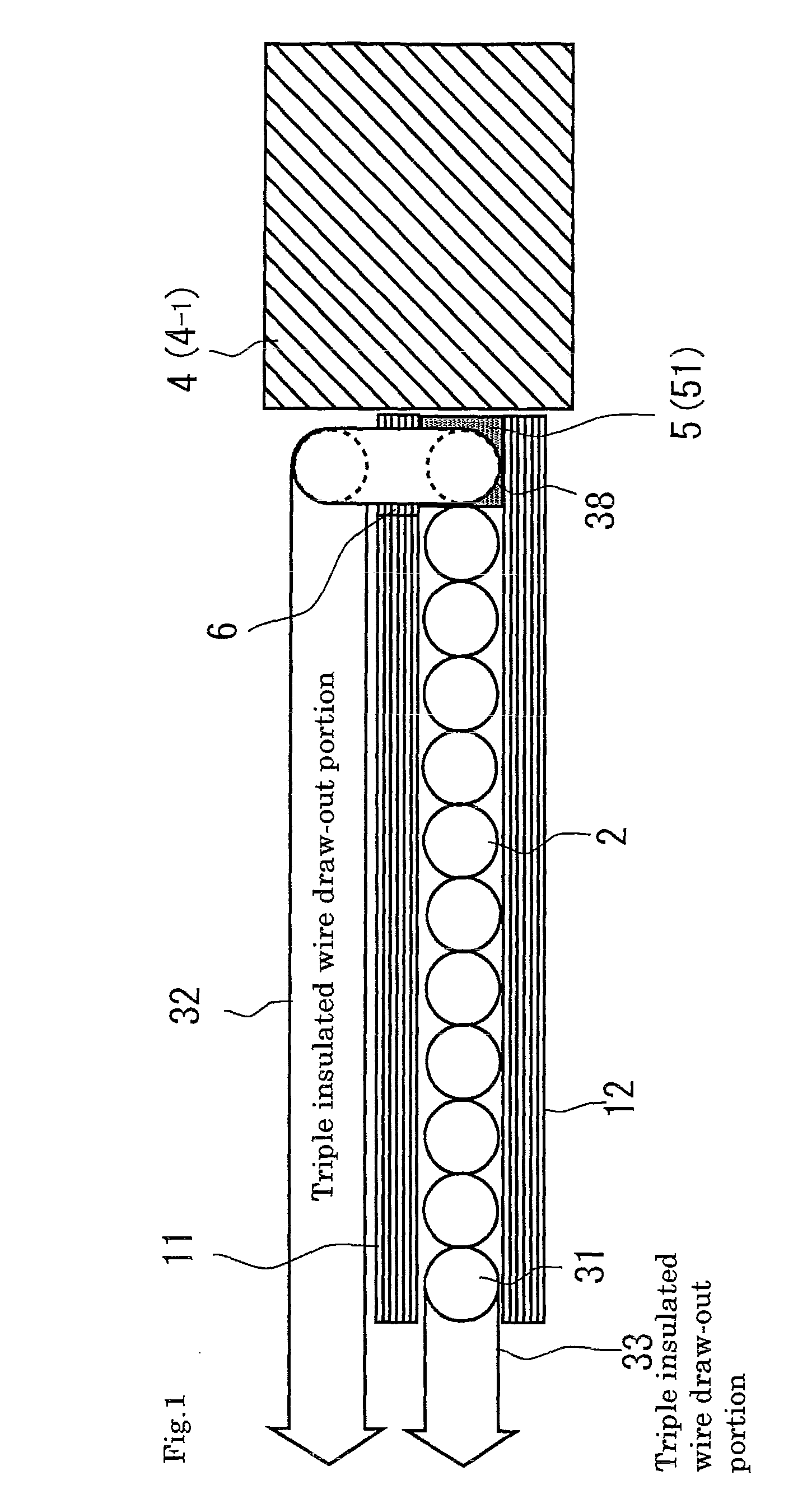
[0052]In FIG. 7, reference numerals 11 and 12 each denote a sheet coil, 25 and 26 denote windings constituted by one triple insulated wire, 25 is a winding wound on the upper surface side of the sheet coli 11, 26 is a winding wound between the sheet coils 11 and 12, and 5 and 5 each denote a spacer. Reference numerals 34 and 35 denote winding start portions of the windings 25 and 26 respectively, which are connected to each other through a cut portion 6 of the sheet coil 11 and cut portions 51 of the spacers 5. Reference numerals 36 and 37 each denote a triple insulated wire draw-out portion. Reference numeral 4 denotes a magnetic core (4-1 denotes a magnetic core portion positioned inside the winding).
[0053]When forming the transformer 50 according to the present embodiment, the sheet coils 11, 12 and spacers 5, 5 are bonded to...
third embodiment
[0062]FIG. 10 is a cross-sectional view partly illustrating a winding structure of a transformer 70 according to the third embodiment of the present invention.
[0063]In FIG. 10, reference numerals 13 and 14 each denote a sheet coil, 27 and 28 denote windings constituted by individual triple insulated wires, 27 is a winding wound between the sheet coils 13 and 14, 28 is a winding wound on the lower surface side of the sheet coil 14, 73 to 76 each denote a triple insulated wire draw-out portion, and 5 and 5 each denote a spacer. Reference numeral 4 denotes a magnetic core (4-1 denotes a magnetic core portion positioned inside the winding). A reference numeral 77 denotes a winding start portion of the winding 27, which is connected to the triple insulated wire draw-out portion 73 through a cut portion 61 of the sheet coil 13 and cut portion 51 of the spacer 5. A reference numeral 78 denotes a winding start portion of the winding 28, which is connected to the triple insulated wire draw-o...
PUM
 Abstract
Description
Claims
Application Information
 - R&D
- Intellectual Property
- Life Sciences
- Materials
- Tech Scout
- Unparalleled Data Quality
- Higher Quality Content
- 60% Fewer Hallucinations
Browse by: Latest US Patents, China's latest patents, Technical Efficacy Thesaurus, Application Domain, Technology Topic, Popular Technical Reports.
© 2025 PatSnap. All rights reserved.Legal|Privacy policy|Modern Slavery Act Transparency Statement|Sitemap|About US| Contact US: help@patsnap.com


