

Underwater structures
- Summary
- Abstract
- Description
- Claims
- Application Information
AI Technical Summary
Benefits of technology
Problems solved by technology
Method used
Image

Examples
first embodiment
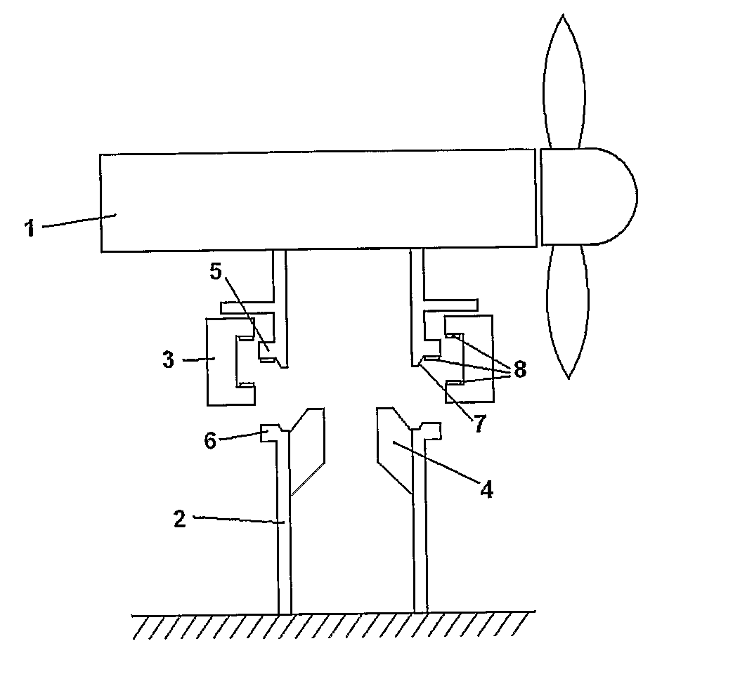
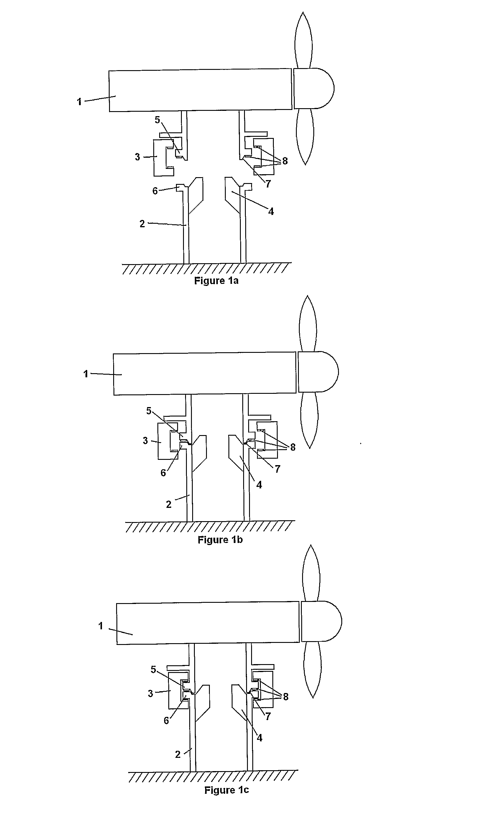
[0030]FIGS. 1a, 1b and 1c show respective cross sectional views through an underwater current turbine device. The underwater device comprises a power generating apparatus (PGA) 1, and a support structure 2. The support structure 2 is mounted on an underwater surface, such as a seabed or riverbed. Although a current turbine device is shown and described in the following, it should be understood that the principles of the present invention are applicable also to wave power generation devices. FIG. 1a shows the PGA 1 positioned above the support structure 2, ready to be connected thereto. The PGA 1 could be supported by a crane (not shown) or could be positively buoyant and connected to the support structure by a winch. The PGA 1 is manoeuvred into place on the support structure 2, the result of which is illustrated in FIG. 1b. In this first embodiment of the present invention, fixed alignment guides 4 mounted to the support structure help to guide the PGA 1 into place. The fixed align...
second embodiment
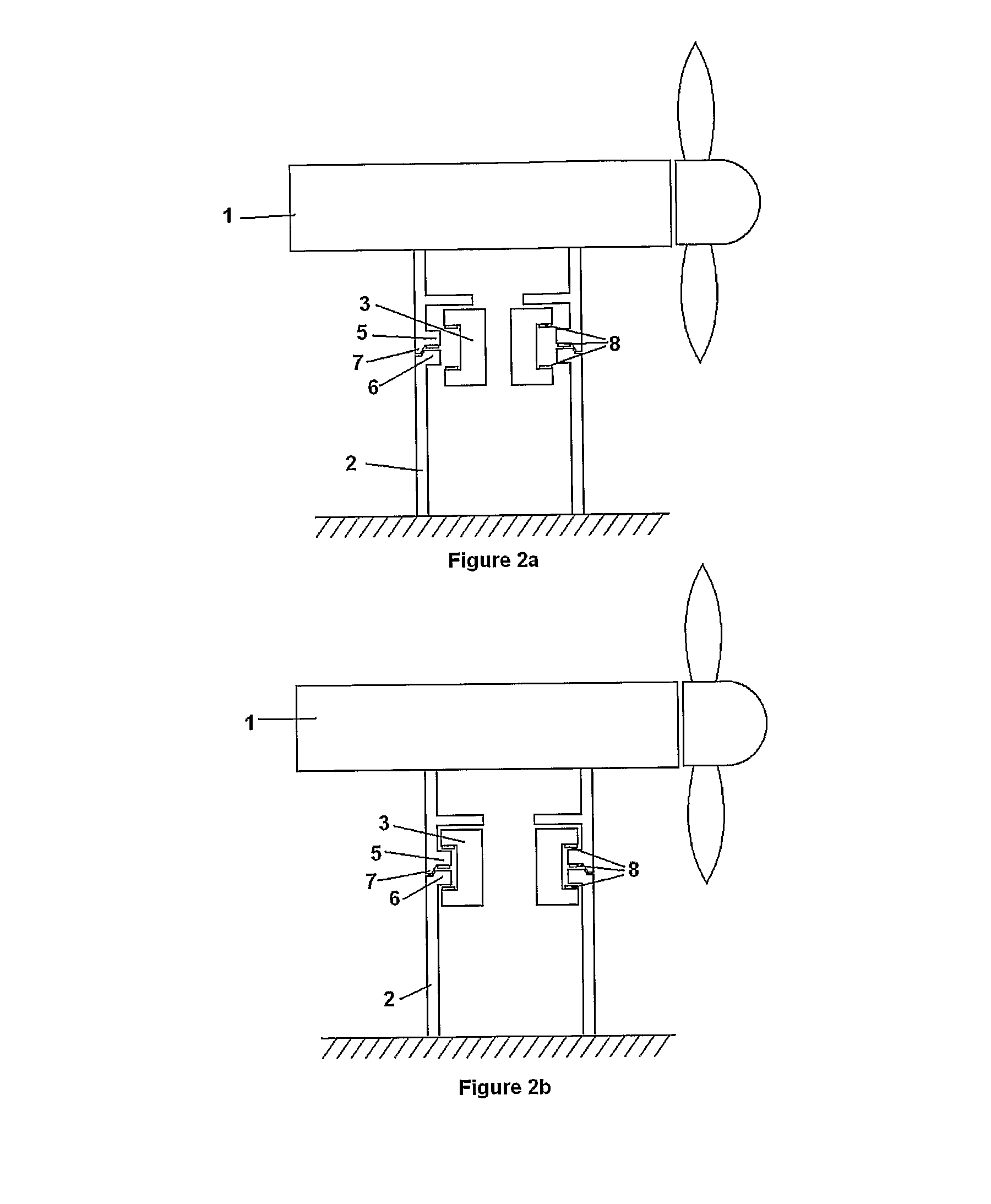
[0033]FIGS. 2a and 2b illustrate respective cross sections of a second embodiment in which the moveable elements 3 are located inside the PGA 1, and are actuated radially outwards to secure the coupling. FIG. 2a shows the PGA 1 mounted on the support structure 2 with the moveable elements 3 in the release position, that is disengaged. In FIG. 2b, the moveable elements 3 have been actuated radially outwards to the engaged position to secure the coupling.
third embodiment
[0034]FIGS. 3a, 3b, and 3c show respective cross sections of a third embodiment in which the moveable elements 3 perform the dual function of a yaw bearing and, upon further tightening of the actuators, a friction brake to prevent the yaw bearing rotating about the vertical axis. In FIG. 3a the PGA 1 is mounted on the support structure 2 with the moveable elements 3 disengaged. In this embodiment, the moveable elements 3 and the mating features 5 and 6 on the PGA 1 and support structure 2 are tapered. In FIG. 3b the moveable elements 3 have been actuated radially inwards (actuator not shown) such that there remains sufficient clearance between the mechanical elements 3 and the mating features on the PGA 5 and support structure 6 for the yaw bearing to turn freely. In FIG. 3c, the coupling has been tightened by further actuation of the moveable elements 3 radially inwards, such that tapered faces of the moveable elements 3 bear against corresponding faces on the mating features 5 and...
PUM
 Abstract
Description
Claims
Application Information