
Substrate holder mounting device and substrate holder container chamber

a technology for mounting devices and substrates, which is applied in the manufacture of record carriers, coatings, electrical devices, etc., can solve the problems of difficult to reduce the size of the substrate holder container chamber, useless space at the outer periphery, etc., and achieve the effect of reducing the size of the chamber, simplifying the device configuration, and saving the space of the devi

Inactive Publication Date: 2010-05-27
CANON ANELVA CORP
View PDF1 Cites 6 Cited by
  • Summary
  • Abstract
  • Description
  • Claims
  • Application Information

AI Technical Summary

Benefits of technology

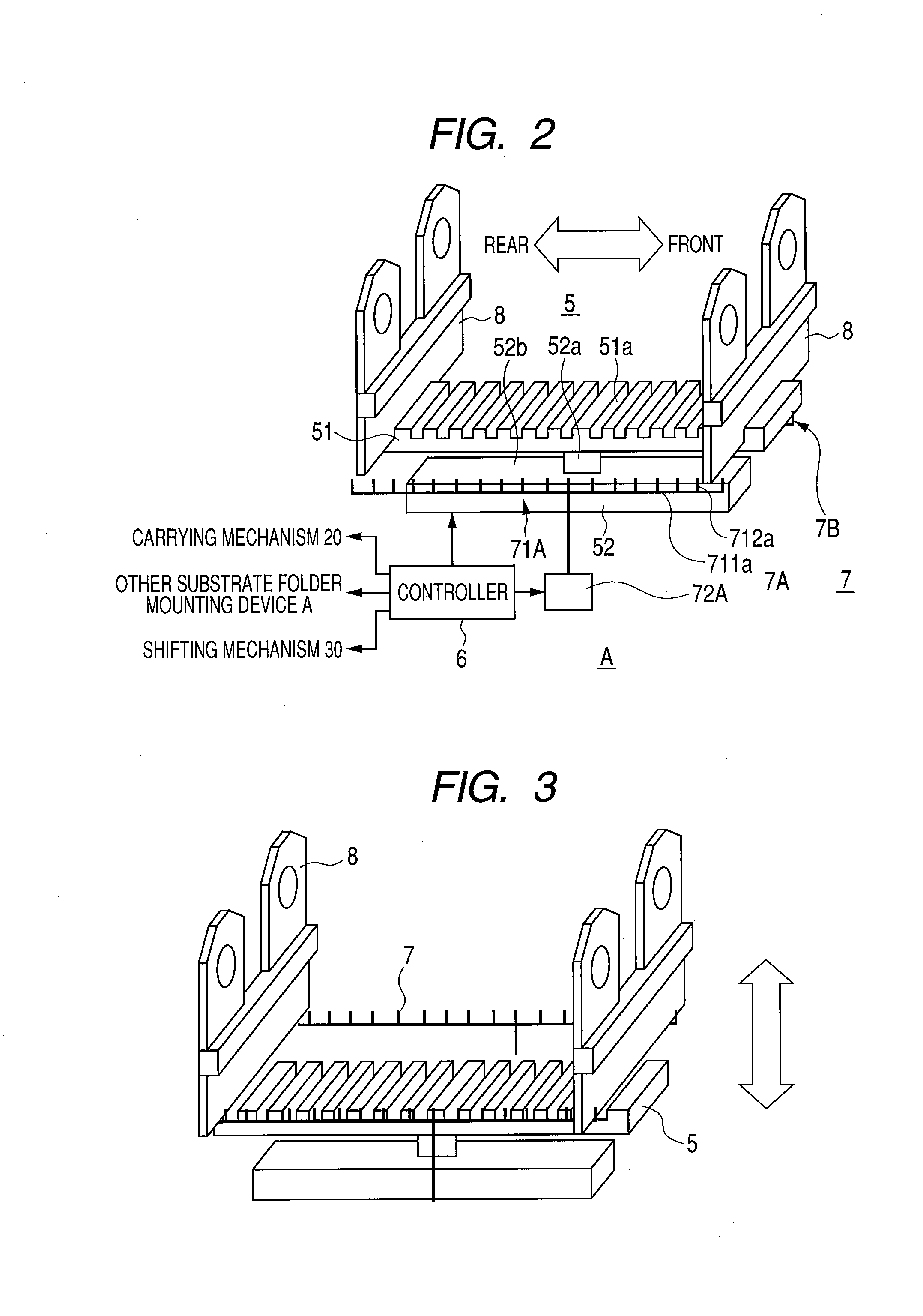
The present invention provides a substrate holder mounting device that can simplify the device configuration, space-saving, and improve heating efficiency. The device includes a table mechanism for mounting multiple substrate holders, an up / down mechanism for separating the substrate holders from the table mechanism, and a link-up mechanism that moves the positions of the substrate holders on the table mechanism. The carrying rails can be arranged in parallel instead of being radially arranged, which reduces the size of the chamber and improves heating efficiency.

Problems solved by technology

However, there have been following problems or issues on the above system.
In addition, as a feature of the radial arrangement, a carrying rail spacing near a center expands toward an outer periphery according to an angle of radiation, so that a useless space occurs at the outer periphery.
These problems have made it difficult to reduce a size of the substrate holder container chamber.

Method used


Image

  • Substrate holder mounting device and substrate holder container chamber
  • Substrate holder mounting device and substrate holder container chamber
  • Substrate holder mounting device and substrate holder container chamber

Examples


Embodiment Construction

Description of Substrate Processing Device Configuration

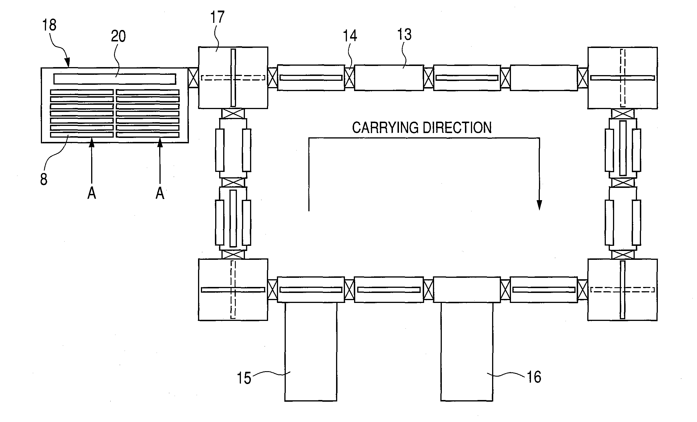
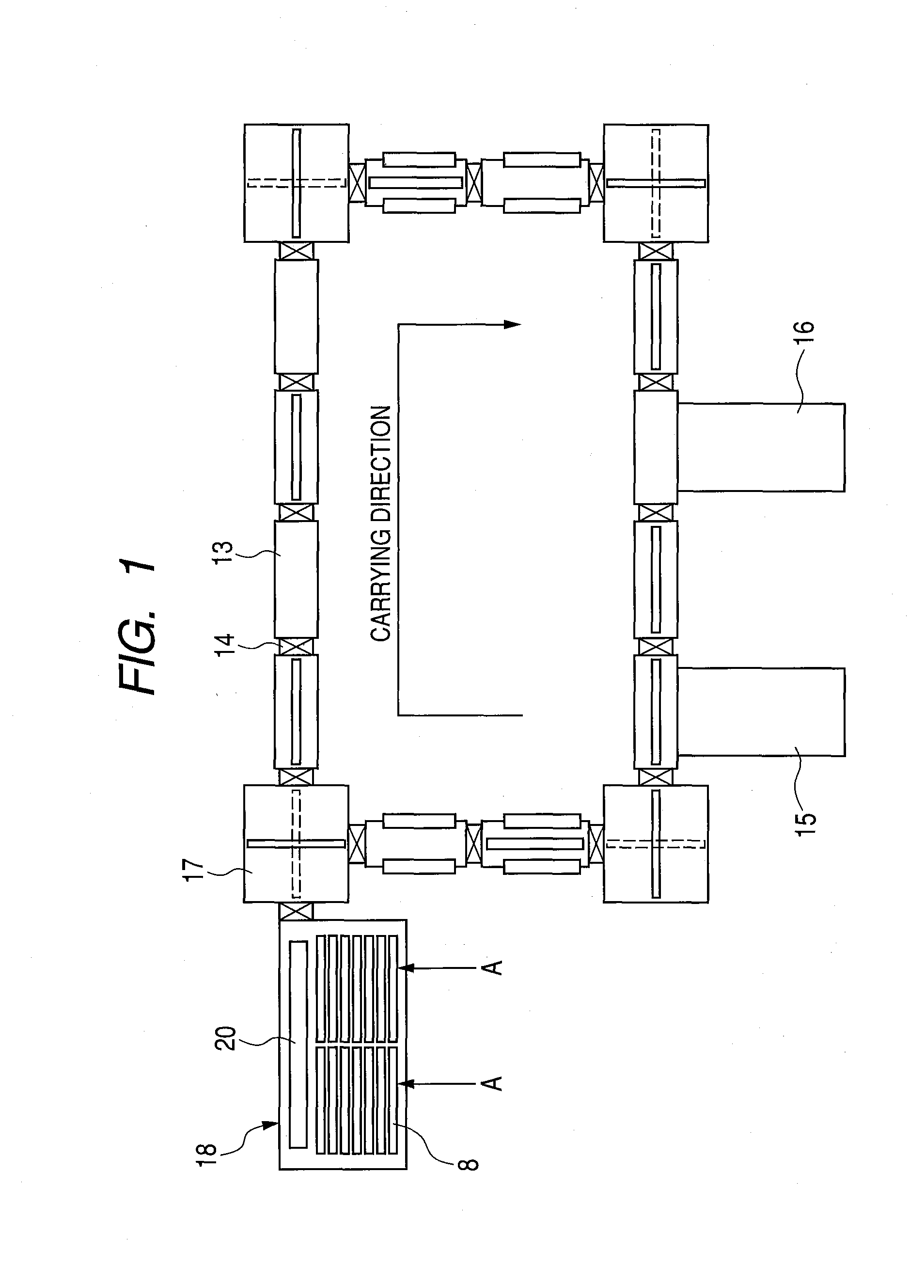
[0025]FIG. 1 is a plan view showing a schematic configuration of an in-line type substrate processing device according to the present embodiment. Such the in-line type substrate processing device is, for example, used as a device for manufacturing magnetic disks. In the substrate processing device of the present embodiment, a plurality of vacuum chambers 13 are arranged in a state of being connected to each other in an endless form (rectangular-shaped loop in FIG. 1). Each vacuum chamber 13 is a vacuum container in which gases are exhausted by an exclusive or nonexclusive exhaust system. A gate valve 14 is arranged at a boundary of each vacuum chamber 13, and the vacuum chambers 13 are connected to each other with an airtight state being kept therein. A substrate is held to be carried by a substrate holder 8 through a substrate processing device. A transport path is provided in the plurality of connected vacuum chambers 13, and...


PUM

PropertyMeasurementUnit
magneticaaaaaaaaaa
angle of radiationaaaaaaaaaa
sizeaaaaaaaaaa

Abstract

A substrate holder mounting device is provided that is compact and has a simple structure. The substrate holder mounting device according to the present invention is provided with: a first and a second mounting mechanisms (5, 7) that are housed in a chamber and that are respectively configured to be capable of mounting a plurality of substrate holders along a row; row direction drive means that moves the first mounting mechanism to a row direction relatively with respect to the second mounting mechanism; a shifting mechanism (30) that shifts the substrate holders between the first and second mounting mechanisms; and a link-up mechanism that changes positions of the substrate holders in the row direction in the first or second mounting mechanism by a linkage between the shifting mechanism and the above-described row direction drive means.

Description

CROSS-REFERENCES TO RELATED APPLICATIONS[0001]This application is a continuation application of International Application No. PCT / JP2008 / 067737, filed on Sep. 30, 2008, the entire contents of which are incorporated by reference herein.BACKGROUND ART[0002]As a measure against a deposited film on a substrate holder generated in an in-line type substrate processing device, an exchange system of the substrate holders using a substrate holder container chamber is disclosed in Patent Document 1.[0003]The substrate holder container chamber disclosed in Patent Document 1 is provided with a radially arranged plurality of carrying rails with carrying rollers, and a carrying rail rotating mechanism that rotationally drives the carrying rails with a center of radiation being as an axis, and substrate holders can be loaded on each carrying rail. The system described above is a system in which the substrate holders in the container chamber is carried out (collected) to the in-line type substrate ...

Claims


Application Information

Patent Timeline
Patent Type & Authority Applications(United States)
IPC IPC(8): G11B5/84B05C13/02
CPCH01L21/67346H01L21/67313
Inventor HIGASHISAKA, RYUJIWAKABAYASHI, HIDEKI
Owner CANON ANELVA CORP
Learn More