

Fuel cell
- Summary
- Abstract
- Description
- Claims
- Application Information
AI Technical Summary
Benefits of technology
Problems solved by technology
Method used
Image

Examples
first embodiment
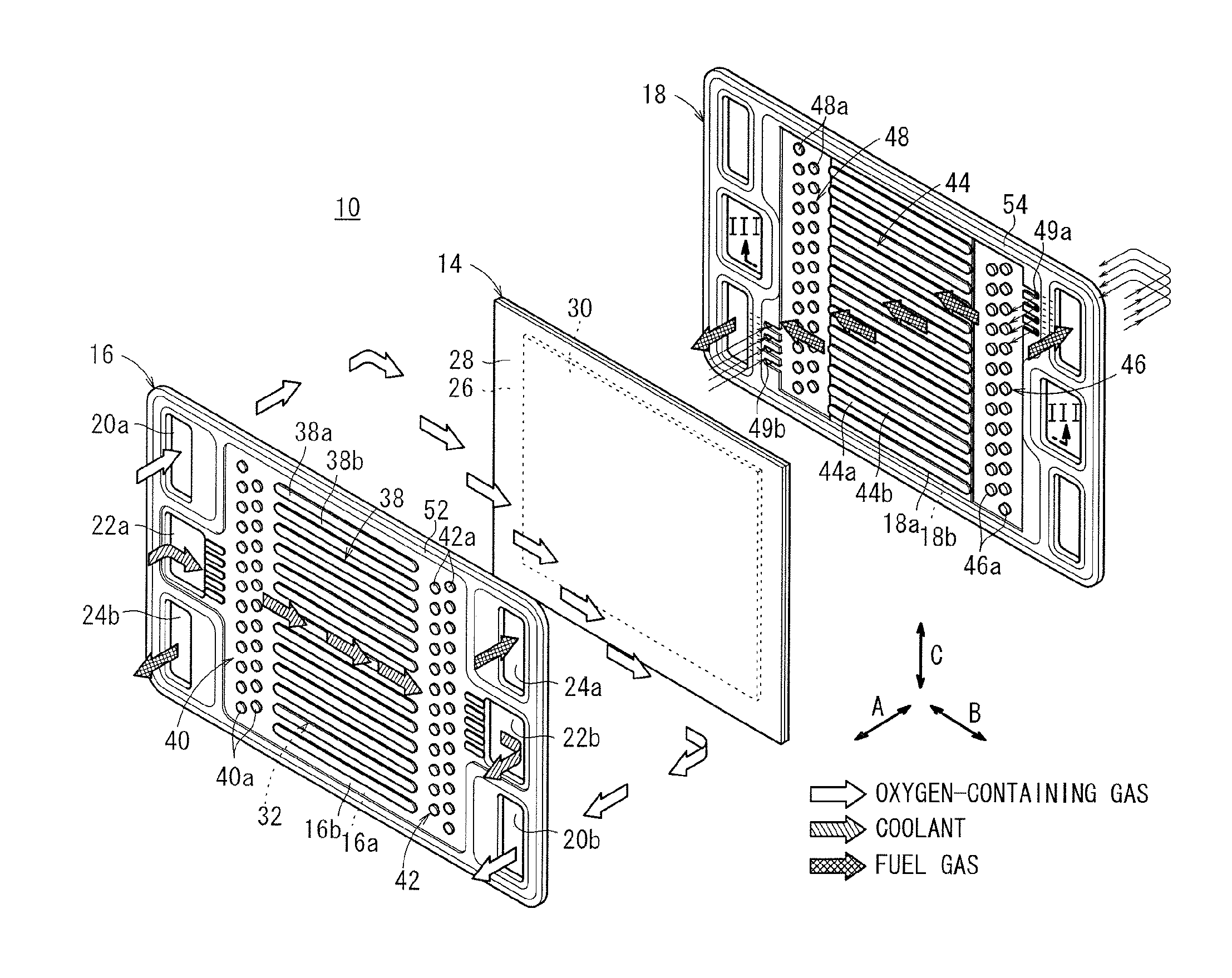
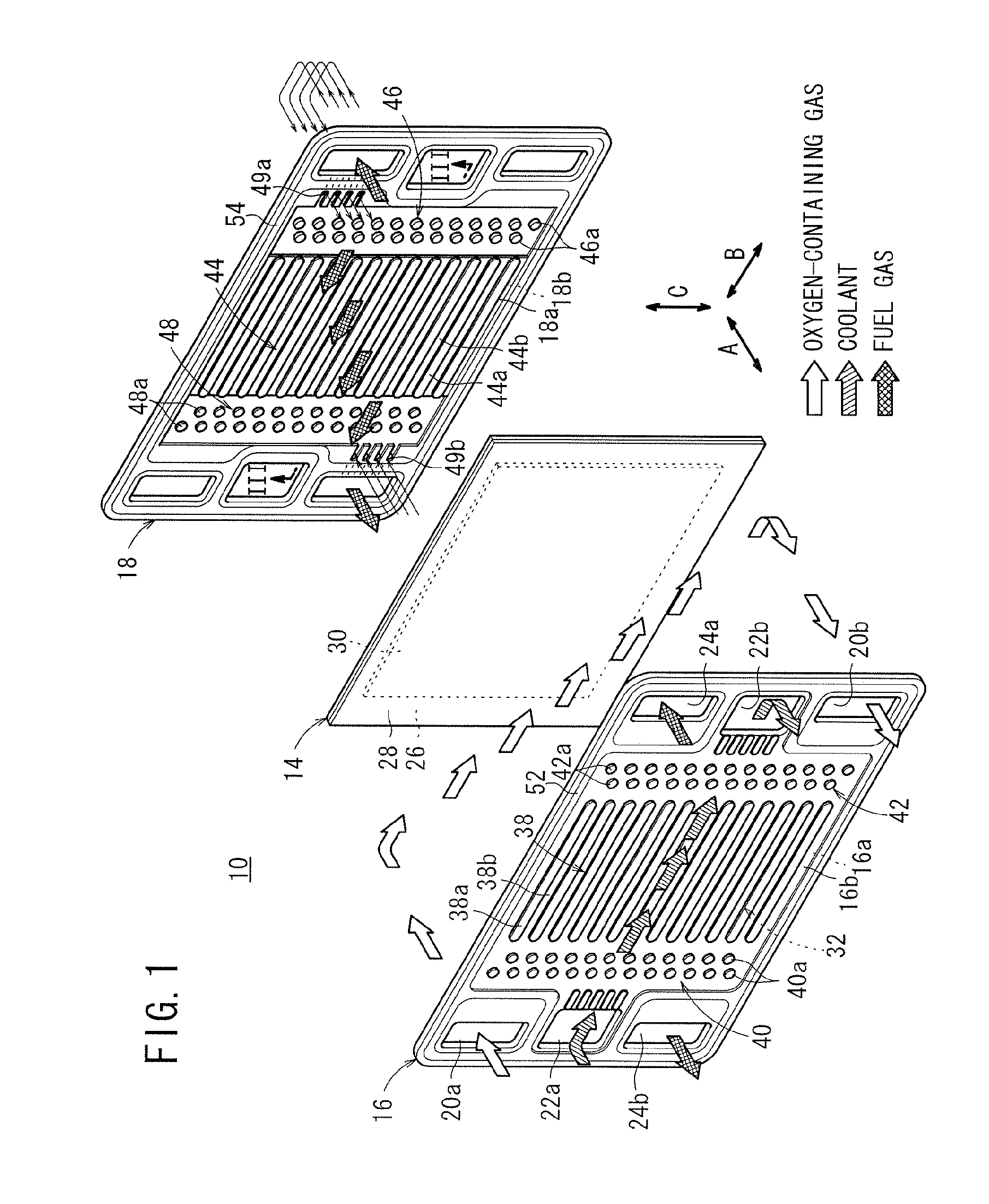
[0028]As shown in FIG. 1, a fuel cell 10 according to the present invention is formed by sandwiching a membrane electrode assembly 14 between a first separator (cathode side separator) 16 and a second separator (anode side separator) 18. For example, the first and second separators 16, 18 are carbon separators. Alternatively, the first and second separators 16 may be steel plates, stainless steel plates, aluminum plates, plated steel sheets, or metal plates having anti-corrosive surfaces by surface treatment.
[0029]At one end of the fuel cell 10 in a horizontal direction indicated by an arrow B in FIG. 1, an oxygen-containing gas supply passage 20a for supplying an oxygen-containing gas (reactant gas), a coolant supply passage 22a for supplying a coolant, and a fuel gas discharge passage 24b for discharging a fuel gas (reactant gas) such as a hydrogen-containing gas are arranged in a vertical direction indicated by an arrow C. The oxygen-containing gas supply passage 20a, the coolant...
third embodiment
[0059]FIG. 7 is an exploded perspective view showing a fuel cell 70 according to the present invention.
[0060]The fuel cell 70 is formed by sandwiching a membrane electrode assembly 14 between a first separator 16 and a second separator (anode side separator) 72. The second separator 72 has an inlet buffer 46 connected to the inlet of the fuel gas flow field 44 and an outlet buffer 74 connected to the outlet of the fuel gas flow field 44.
[0061]As shown in FIGS. 7 and 8, a shallow groove area 74a having a small depth H2 is formed at least in part of the outlet buffer 74. The shallow groove area 74a becomes narrow as it gets remoter from the fuel gas discharge passage 24b. That is, the shallow groove area 74a has a substantially triangular shape. The depth in the other portion of the outlet buffer 74 is determined to be equal to the depth H1 in the inlet buffer 46 (H1>H2).
[0062]In the third embodiment, the shallow groove area 74a is formed at least in part of the outlet buffer 74. Thus...
fourth embodiment
[0063]FIG. 9 is a front view showing a second separator (anode side separator) 80 of a fuel cell according to the present invention.
[0064]The second separator 80 has an inlet buffer 82 connected to the inlet of the fuel gas flow field 44 and an outlet buffer 84 connected to the outlet of the fuel gas flow field 44.
[0065]The inlet buffer 82 has a plurality of grooves 82b formed by protrusions 82a such as curved narrow ridges and a substantially triangular block. Likewise, the outlet buffer 84 has a plurality of grooves 84b formed by protrusions 84a such as curved narrow ridges and a substantially triangular block. The groove width S1 of the grooves 82b is wider than the groove width S2 of the grooves 84b (S1>S2). Thus, the pressure loss in the inlet buffer 82 is smaller than the pressure loss in the outlet buffer 84.
[0066]In the fourth embodiment, since the grooves 82b of the inlet buffer 82 are wider than the grooves 84b of the outlet buffer 84, the pressure loss in the inlet buffer...
PUM
 Abstract
Description
Claims
Application Information