Duty cycle adjustment for a local oscillator signal

a local oscillator and duty cycle technology, applied in the field of radio frequency (rf) communication, can solve the problems of significant interference problems, ber degradation in digital rf systems, audible and/or visible signal-to-noise ratio (snr) degradation in analog rf systems, and difficulty in providing an interference-tolerant rf receiver design

Active Publication Date: 2010-05-27
QUALCOMM INC
View PDF99 Cites 31 Cited by
  • Summary
  • Abstract
  • Description
  • Claims
  • Application Information

AI Technical Summary

Problems solved by technology

These interfering signals may have originated from users in adjacent channels and/or from transmission sources which may be relatively far removed in frequency from the channel of interest but whose large transmission power may still cause significant interference problems.
The effect of interfering signals in the channel of interest may result in, for example, bit error rate (BER) degradation in digital RF systems and audible and/or visible signal-to-noise ratio (SNR) degradation in analog RF systems.

Method used


Image

  • Duty cycle adjustment for a local oscillator signal
  • Duty cycle adjustment for a local oscillator signal
  • Duty cycle adjustment for a local oscillator signal

Examples


Embodiment Construction

[0016]The following description and drawings are illustrative of aspects and examples of the invention and are not to be construed as limiting the invention. Numerous specific details are described to provide a thorough understanding of the present invention. However, in certain instances, well-known or conventional details are not described in order to avoid obscuring the description of the present invention. References to one embodiment or an embodiment in the present disclosure are not necessarily to the same embodiment, and such references may include one or more embodiments.

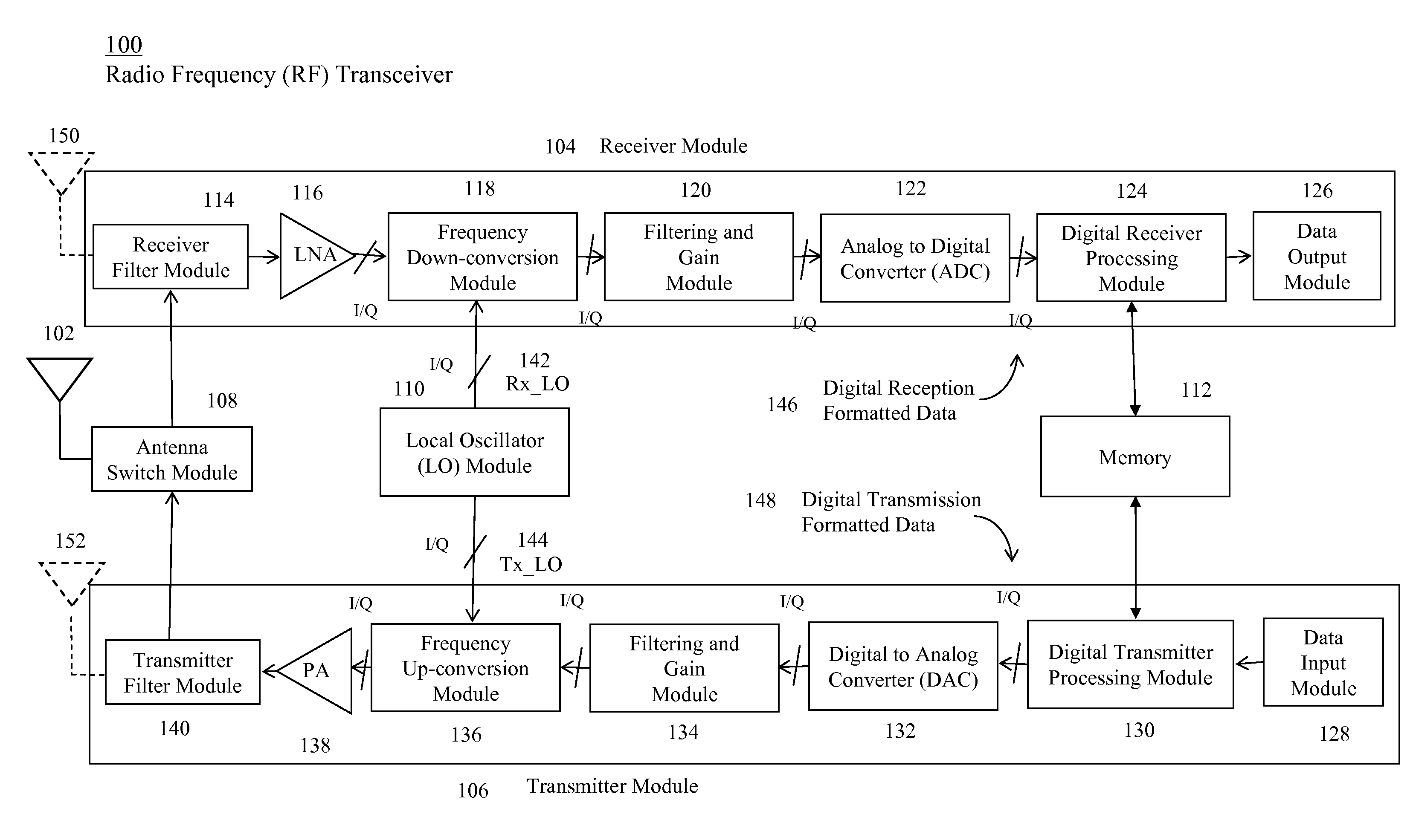
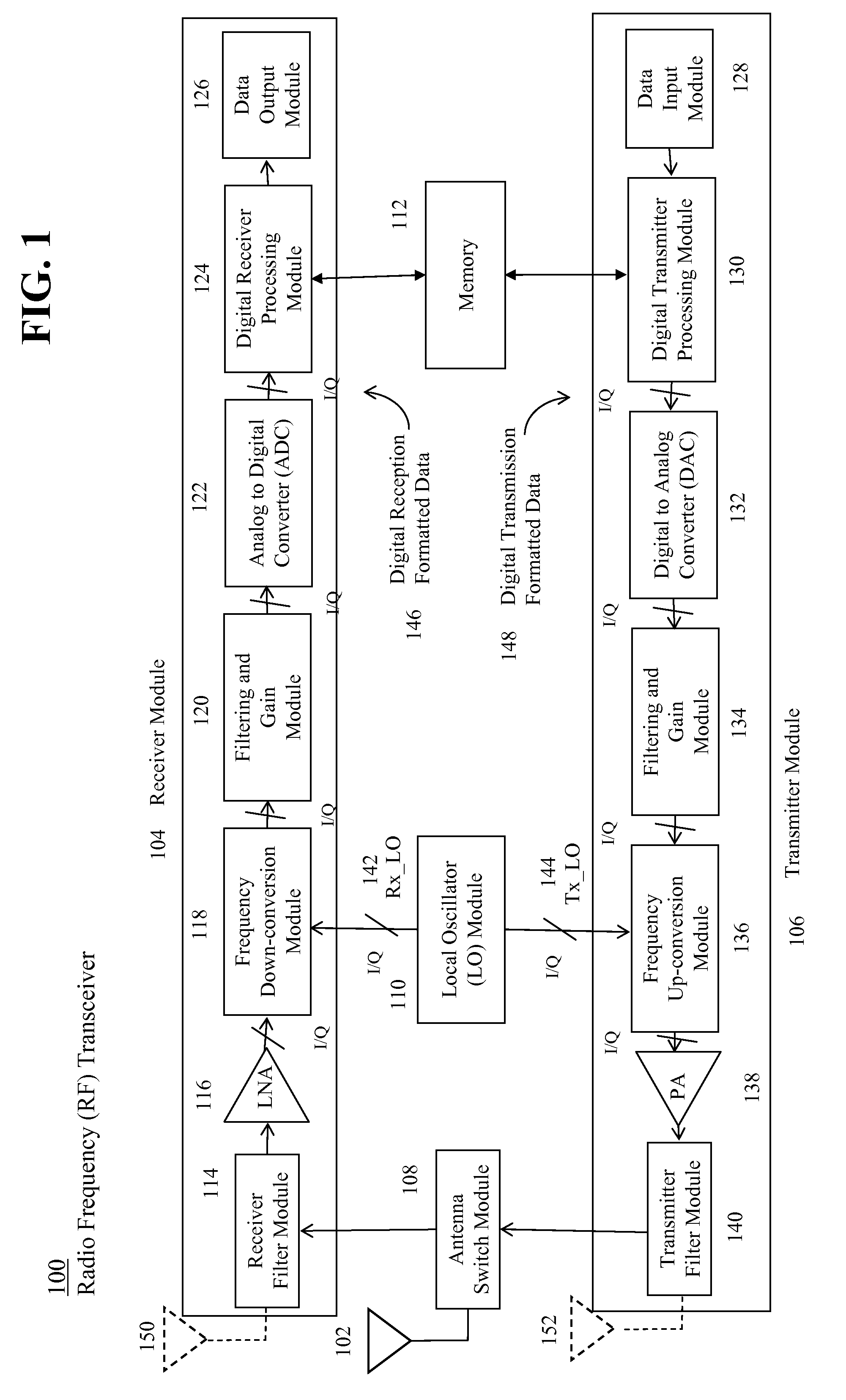
[0017]FIG. 1 illustrates a block diagram representation of a radio frequency (RF) transceiver 100, according to one aspect of the present invention. The RF transceiver 100 includes an antenna 102, a receiver module 104, a transmitter module 106, an antenna switch module 108, a local oscillator (LO) module 110, and a memory 112. In practice, not every RF transceiver design will have all of the elements shown ...


PUM


Abstract

A local oscillator (LO) module comprises a local oscillator and a feedback circuit. The local oscillator, biased at a supply voltage, generates a local oscillator signal having a duty cycle. The feedback circuit makes an absolute adjustment of the duty cycle of the local oscillator signal in response to a difference between a first voltage signal, representing a voltage level of the local oscillator signal, and a second voltage signal, representing a voltage level of a portion of the supply voltage corresponding to a desired duty cycle for the local oscillator signal.

Description

FIELD OF THE INVENTION[0001]The present invention generally relates to radio frequency (RF) communications. More particularly, the present invention relates to adjusting a duty cycle of a local oscillator signal employed in a RF communications.BACKGROUND OF THE INVENTION[0002]In radio frequency (RF) communication applications, a RF receiver or a receiver portion of an RF transceiver is an electronic circuit that receives an input from an antenna, and uses electronic filters to separate a radio signal of interest from all other radio signals received by the antenna. An amplifier amplifies the radio signal of interest to a level suitable level for processing. A local oscillator generates a local oscillator signal for a mixer to convert the amplified the radio signal of interest to a different frequency. The converted frequency signal is further filtered, amplified, demodulated, and decoded into a usable form, such as sound, pictures, digital data, measurement values, navigational posi...

Claims


Application Information

Patent Timeline
IPC IPC(8): H04B1/40
CPCH03L7/08H03K3/017H03K5/1565H03K5/156H04B1/16
Inventor PANIKKATH, VINOD V.LIU, LI
Owner QUALCOMM INC
Why Eureka
Try Eureka