Method and apparatus for displaying a field of a brain of a patient and navigation system for brain surgery

a technology of brain surgery and display field, which is applied in the field of methods and apparatus for displaying the field of the brain of a patient, can solve the problems of large artifacts in the functional information which can only be corrected later only hardly, and the time resolution is relative coarse, and achieves the effect of facilitating the interpretation of laser doppler images

Inactive Publication Date: 2010-05-27
CARL ZEISS SURGICAL
View PDF6 Cites 17 Cited by
  • Summary
  • Abstract
  • Description
  • Claims
  • Application Information

AI Technical Summary

Benefits of technology

[0009]According to a further embodiment of the method the acquiring the images comprises detecting measuring light, wherein intensities of the detected measuring light having wavelengths greater than 1300 nm and smaller than 600 nm, in particular greater than 820 nm and smaller than 780 nm, amount to less than 10% of a total intensity of the detected measuring light. Using light having wavelengths of a thus defined range enables a penetration depth into human tissue, in particular brain tissue, of about 1 mm to 2 mm. In particular, the wavelength range between 600 nm and 1300 nm is referred to as “diagnostic window”. Thus, Laser Doppler signals of particles which are present within this penetration depths and which move relative to each other can be detected. Thereby, the measuring light may exhibit a coherence length which substantially corresponds to twice the penetration depth of the measuring light into a tissue of the brain visible within the illuminated field. Using measuring light having this coherence length enables to detect an interference of light which was reflected by two particles which are a distance apart from each other corresponding to the penetration depth. Thus, it can be ensured that even the light penetrated in deepest locations of the field of the brain may interfere with light which was reflected at the surface of the field of the brain. Thus, a sensitivity may be increased.
[0014]According to a preferred embodiment the at least one determined region may be displayed in superposition with the output image. Possible illustrations thereby comprise encircling the determined region using a line, a coloring the determined region, or the like. Again the illustration is carried out in dependence of the topography data so that the viewer is presented a three-dimensional illustration of the brain allowing an accurate localization of functional areas of the brain.
[0040]According to an embodiment of this aspect of the invention a band-pass filter is arranged in a beam path upstream of the camera, wherein the transmission characteristics of the band-pass filter is adapted such that a transmission of light having wavelengths greater than 1300 nm and smaller than 600 nm, in particular greater than 820 nm and smaller than 780 nm, amounts to less than 10% of a total transmission of the band-pass filter. This enables that only desired light emanating from the field of the brain is detected by the camera. Hereby it is for example possible to use as measuring light a small spectral range of visible light and to concurrently illuminate the field of the brain for visual inspection with white light (light comprising wavelength in the visible range) avoiding disturbing the measurement by this white light reflected at the field of the brain.
[0043]According to an embodiment of this aspect of the present invention the navigation system further comprises a display apparatus for displaying an image in the visible wavelength range, in particular in superposition with analysis image values. Thus, it is further enabled to superimpose details recognizable in the visible wavelength range with details recognizable in the Laser Doppler images. This facilitates an interpretation of the Laser Doppler images by an observer.

Problems solved by technology

A disadvantage of this technique is the relatively coarse time resolution and the high costs.
Otherwise, due to movements of the patient, massive artifacts arise in the functional information which can later only hardly be corrected.

Method used


Image

  • Method and apparatus for displaying a field of a brain of a patient and navigation system for brain surgery
  • Method and apparatus for displaying a field of a brain of a patient and navigation system for brain surgery
  • Method and apparatus for displaying a field of a brain of a patient and navigation system for brain surgery

Examples


Embodiment Construction

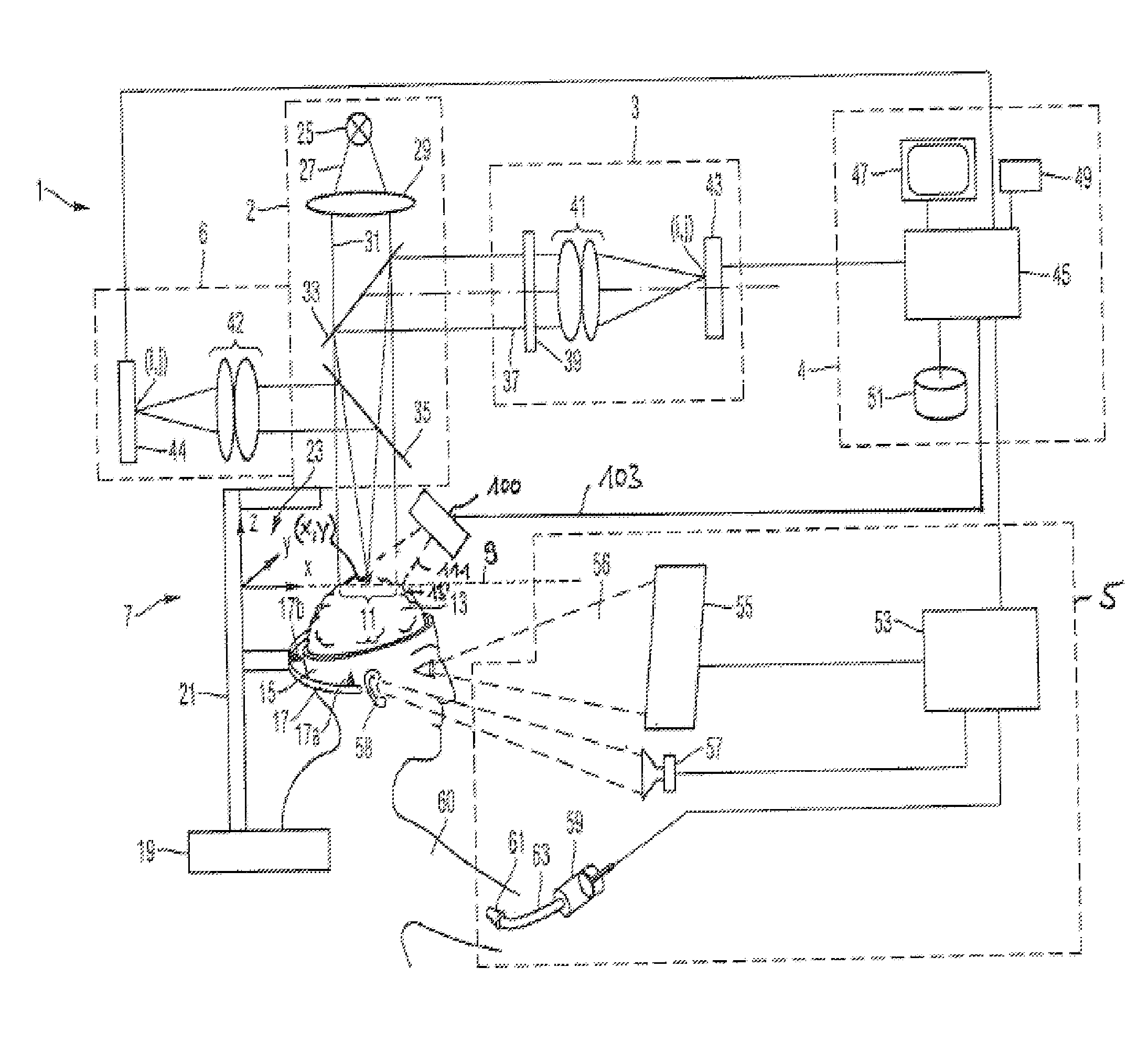
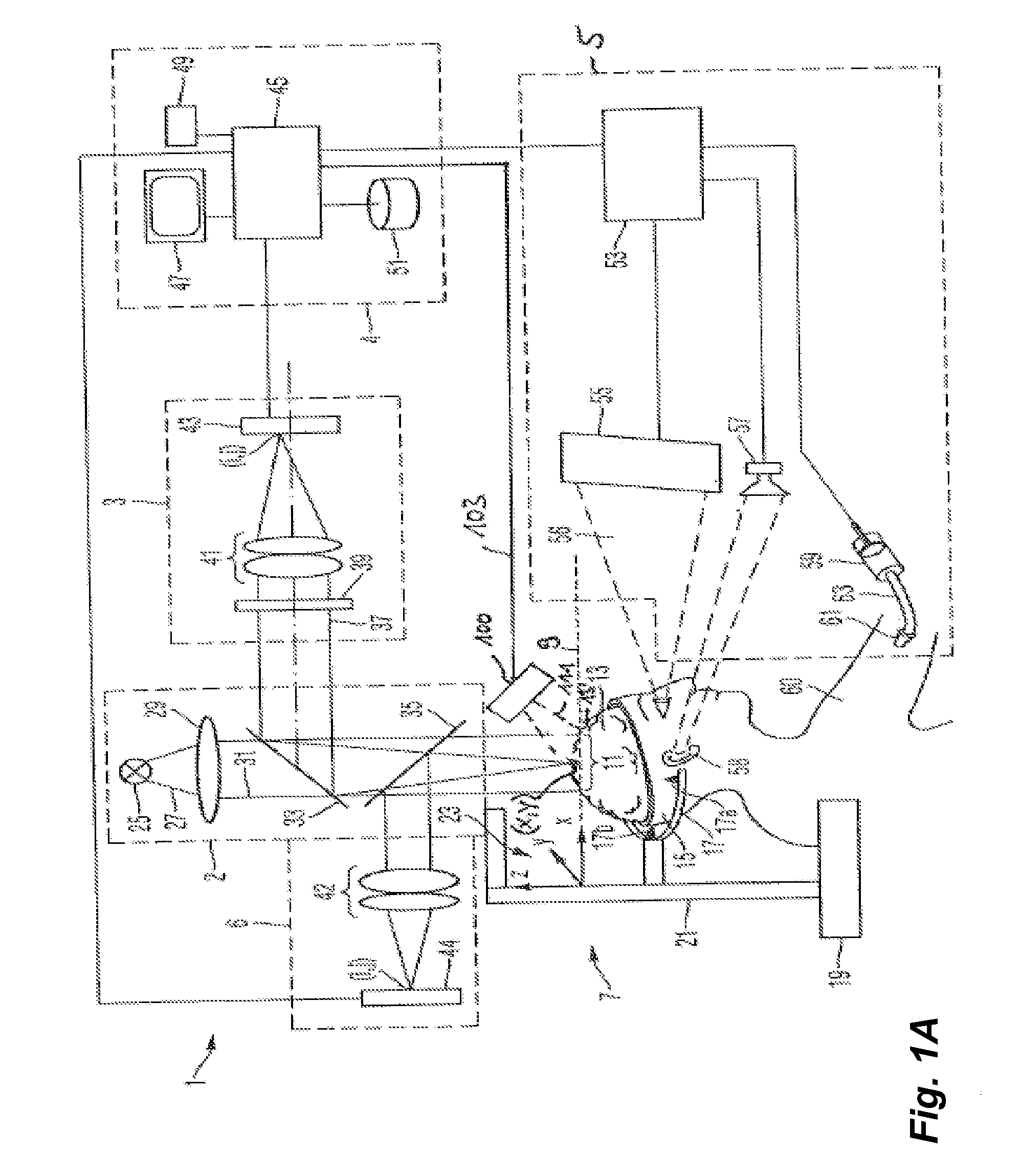
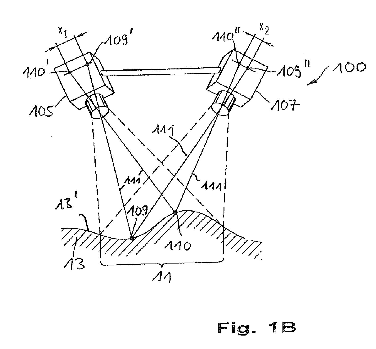
[0055]FIG. 1A shows an embodiment of a navigation system for brain surgeries according to an embodiment of the present invention. The navigation system 1 comprises an imaging system 2, a measuring light camera 3, a control and evaluation unit 4, a white light camera 6, a stimulation apparatus 5, a position acquisition apparatus 7 and an apparatus 100 for acquiring topography data.

[0056]In an object plane 9 of the imaging system 2 a field 11 of a brain 13 of a head 15 is arranged. The head 15 of the patient is connected to a base 19 using a head coupling apparatus 17 via an arrangement of levers 21. Thereby, the head of the patient is held using pins 17a, 17b and a not illustrated pin 17c which are connected to the head coupling apparatus. A coordinate system 23 is connected to the base 19 and thus also to the head coupling apparatus 17. This coordinate system 23 is defined by coordinate axis x, y and z. The imaging system 2 is also connected via the arrangement of levers 21 to the b...


PUM


Abstract

A method and an apparatus for displaying a part of a brain of a patient is provided. Laser Doppler images are acquired before and after a stimulation. The laser Doppler images comprise information about a blood motion or about a perfusion at the acquired part. Then, the blood motion images acquired before and after the stimulation are compared to identify areas in the brain of the patient which are related to the stimulation. The identified areas are displayed in dependence of topography data representing a topography of the brain.

Description

CROSS-REFERENCES TO RELATED APPLICATIONS[0001]This application claims priority to German Patent Application No. DE 10 2008 051 950.2, filed on Oct. 16, 2008. The disclosures of DE 10 2008 051 950.2 is hereby incorporated by reference in its entirety for all purposes. This application is also a continuation-in-part of U.S. patent application Ser. No. 12 / 104,919, filed on Apr. 17, 2008, entitled “Method And Apparatus For Displaying A Field Of A Brain Of A Patient And Navigation System For Brain Surgery,” the disclosure of which is hereby incorporated by reference in its entirety for all purposes.BACKGROUND OF THE INVENTION[0002]This invention relates to a method and an apparatus for displaying a field of a brain of a patient. In particular, this invention relates to a method for determining a continuous field in the brain which is activated or deactivated after a stimulation. Further, the invention relates to a navigation system for brain surgery which is suitable for displaying a fie...

Claims


Application Information

Patent Timeline
Patent Type & Authority Applications(United States)
IPC IPC(8): A61B6/00
CPCA61B5/0059A61B5/0261A61B19/20A61B19/203A61B19/52A61B19/5244A61B2019/5291A61B2017/00066A61B2019/505A61B2019/507A61B2019/5231A61B2019/5255A61B2019/5265A61B2017/00061A61B5/0042A61B5/4064A61B34/20A61B90/10A61B90/14A61B90/36A61B2034/105A61B2034/107A61B2034/2055A61B2034/2065A61B2090/365A61B2090/373
Inventor HAUGER, CHRISTOPHNAHM, WERNERLASSER, THEOLEUTENEGGER, MARCELMARTIN-WILLIAMS, ERICALOPEZ, ANTONIO
Owner CARL ZEISS SURGICAL
Why Eureka
Try Eureka