[0012]This invention is made to solve the problem as described above, and where multiple workpieces in various sizes exist, the robot hand of the present invention can easily have a pair of finger bodies form, in addition to the maximum open clearance, the standby open clearance slightly wider than the external diameter of each workpiece, and can rapidly consecutively form the standby open clearance varying depending on each of various external diameters of the multiple work pieces, thus improving the workability when consecutively or randomly transporting workpieces in various sizes.Means for Solving the Problem
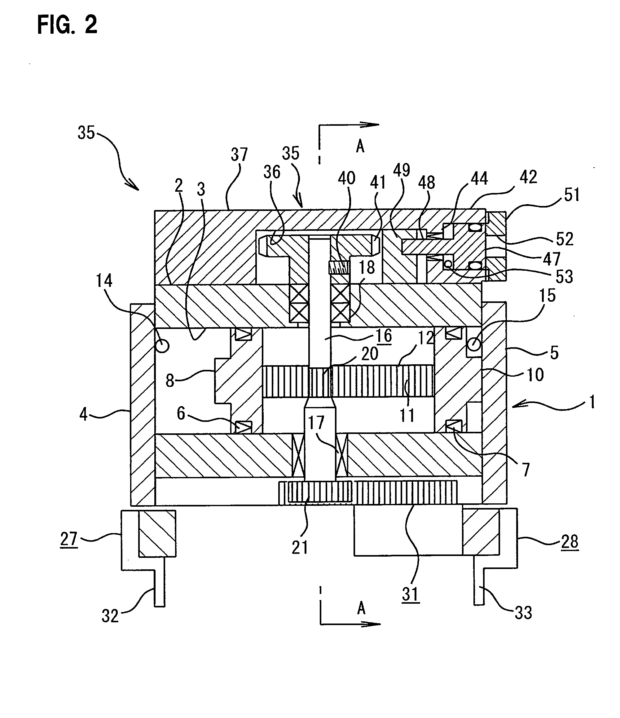
[0014]Furthermore, a driving rack gear is formed on the connection rod, and the driving rack gear engages with a driving
pinion gear arranged on a penetrating axis, which is rotatably arranged in the hand cylinder to penetrate the hand cylinder. Both ends of the penetrating axis protrude from the hand cylinder, and a driven pinion gear is formed on the external periphery of the lower end of the penetrating axis. The driven pinion gear engages with a pair of driven rack gears formed on the pair of finger bodies, so that the pair of finger bodies can slide in an axial direction of the hand cylinder. The stopper mechanism can engage with the penetrating axis protruding upward from the hand cylinder to control a position at which the finger bodies stop. The stopper mechanism may have a stopper gear secured to the upper end of the penetrating axis of the
rack and pinion mechanism and a stopper body arranged reciprocally movably facing the stopper gear to be able to engage with the stopper gear so that the reciprocal movement of the stopper body may be controlled by a detection
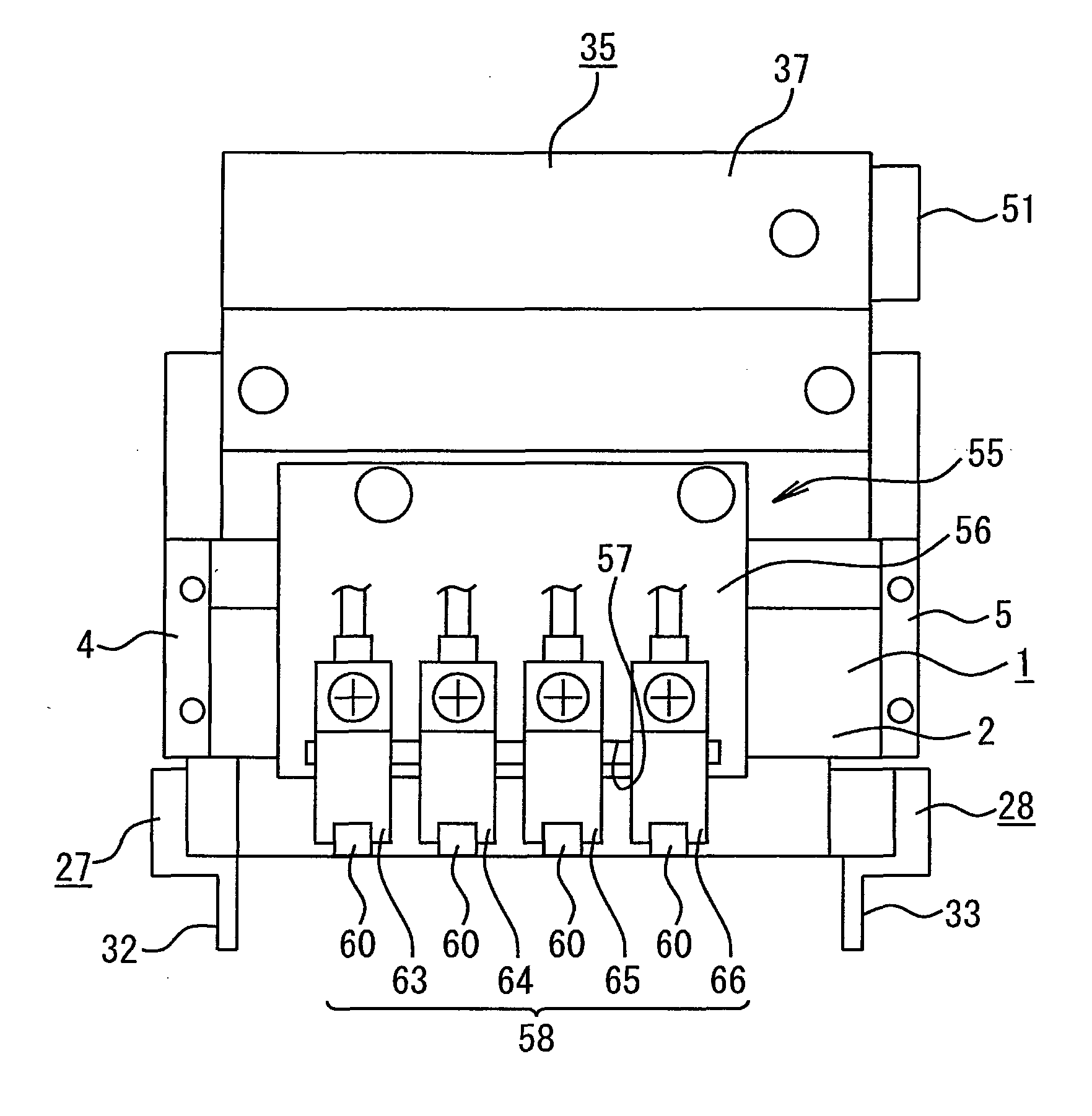
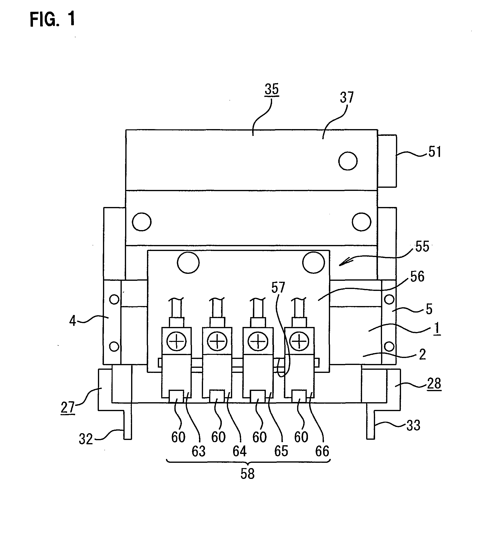
signal of one of the multiple sensors. The sensor mechanism has multiple sensors spaced apart prescribed intervals, and the multiple sensors face an inner portion of a widthwise moving direction of the finger bodies of the
rack and pinion mechanism to be able to detect a position of one of the finger bodies. The multiple sensors may be detachably and movably secured to an elongated hole, formed parallel to the moving direction of the finger bodies, on a sensor plate arranged on the hand cylinder.
[0016]Then, with the one of the multiple sensors being in the state ready for detection, the finger bodies slide inwardly to come close to the one of the multiple sensors ready for detection. The one of the multiple sensors detects the finger bodies, and activates a control device of the stopper mechanism to stop the pair of the finger bodies, thereby forming a standby open clearance between the pair of the finger bodies. The robot hand moves with the formed standby open clearance, and positions the external diameter of the workpiece to be gripped between the standby open clearance of the pair of the finger bodies. Then, the stopper mechanism is released to release the stopped finger bodies, thereby having the finger bodies slide inwardly to narrow the standby open clearance to come in contact with both sides of the workpiece, and thus, the workpiece can be gripped.
[0017]This invention is structured as described above, and accordingly, by rendering one of the multiple sensors in a state ready for detection, the pair of finger bodies can be easily stopped at the one of the multiple sensors ready for detection. Thus, by rendering in a state ready for detection one of the multiple sensors capable of determining a clearance of the pair of finger bodies slightly wider than the external diameter of the workpiece to be griped, the standby open clearance slightly wider than the external diameter of the workpiece to be gripped can be formed. Therefore, by changing one of the sensors to be rendered in a state ready for detection to adjust a position at which the finger bodies stop whenever necessary, the width of the standby open clearance of the finger bodies can be easily and rapidly changed.
[0018]Therefore, where there are multiple workpieces in various sizes, the robot hand of the present invention can easily form the standby open clearance slightly wider than the external diameter of each workpiece, and can rapidly consecutively form the standby open clearance varying depending on various external diameters of the multiple work pieces, thus improving the workability when consecutively or randomly transporting workpieces in various sizes.
