Eureka AIR delivers breakthrough ideas for toughest innovation challenges, trusted by R&D personnel around the world.

Object-Positioning Device for Charged-Particle Beam System

a technology of charged particles and beam systems, applied in the direction of optical radiation measurement, material analysis using wave/particle radiation, instruments, etc., can solve the problems of low-strain region steep deterioration of damping alloy damping characteristics, relative vibration between rotation control members and inertial members, etc., to improve the spatial resolution of charged particle beam systems, reduce the effect of small vibrations

Active Publication Date: 2010-06-03
JEOL LTD
View PDF4 Cites 6 Cited by
  • Summary
  • Abstract
  • Description
  • Claims
  • Application Information

AI Technical Summary

Benefits of technology

[0017]It is an object of the present invention to provide an object-positioning device which suppresses very small vibrations by a simple assembly and thus improves the spatial resolution of a charged-particle beam system such as an electron microscope.
[0020]Preferably, the first vibration-suppressing member is made of a viscoelastic material having a large loss coefficient to widen the frequency range of operation of the vibration-absorbing portion.
[0022]Preferably, the second vibration-suppressing member is made of a viscoelastic material having a large loss coefficient to widen the frequency range of operation of the vibration-absorbing portion.
[0023]According to the present invention, vibrations of the sample in the directions of the various axes are suppressed. This improves the spatial resolution of a transmission electron microscope. The vibration-suppressing portion mounted on the end (atmospheric side) of the sample holder directly suppresses vibrations of the holder and so the structure is simplified. Also, the manufacturing cost can be suppressed.

Problems solved by technology

When the movable aperture device vibrates around the center of rotation as if it rocks, relative vibrations occur between the rotation control member and the inertial member.
Also, the structure of the instrument is complicated.
Furthermore, generally, the damping characteristics of damping alloys deteriorate steeply in a low-strain region.
In addition, damping alloys are expensive and increase the manufacturing cost.

Method used


Image

  • Object-Positioning Device for Charged-Particle Beam System
  • Object-Positioning Device for Charged-Particle Beam System
  • Object-Positioning Device for Charged-Particle Beam System

Examples


Embodiment Construction

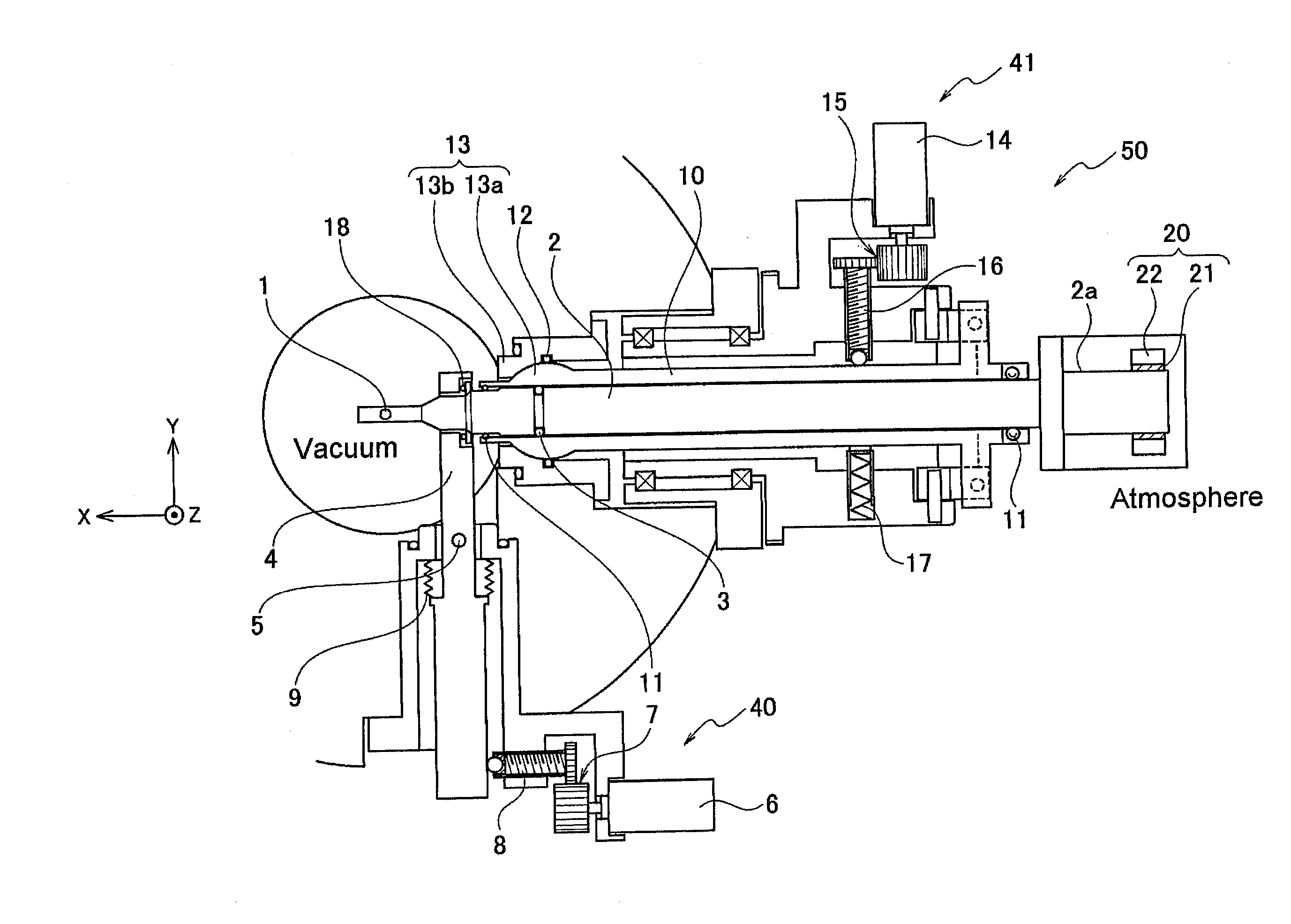
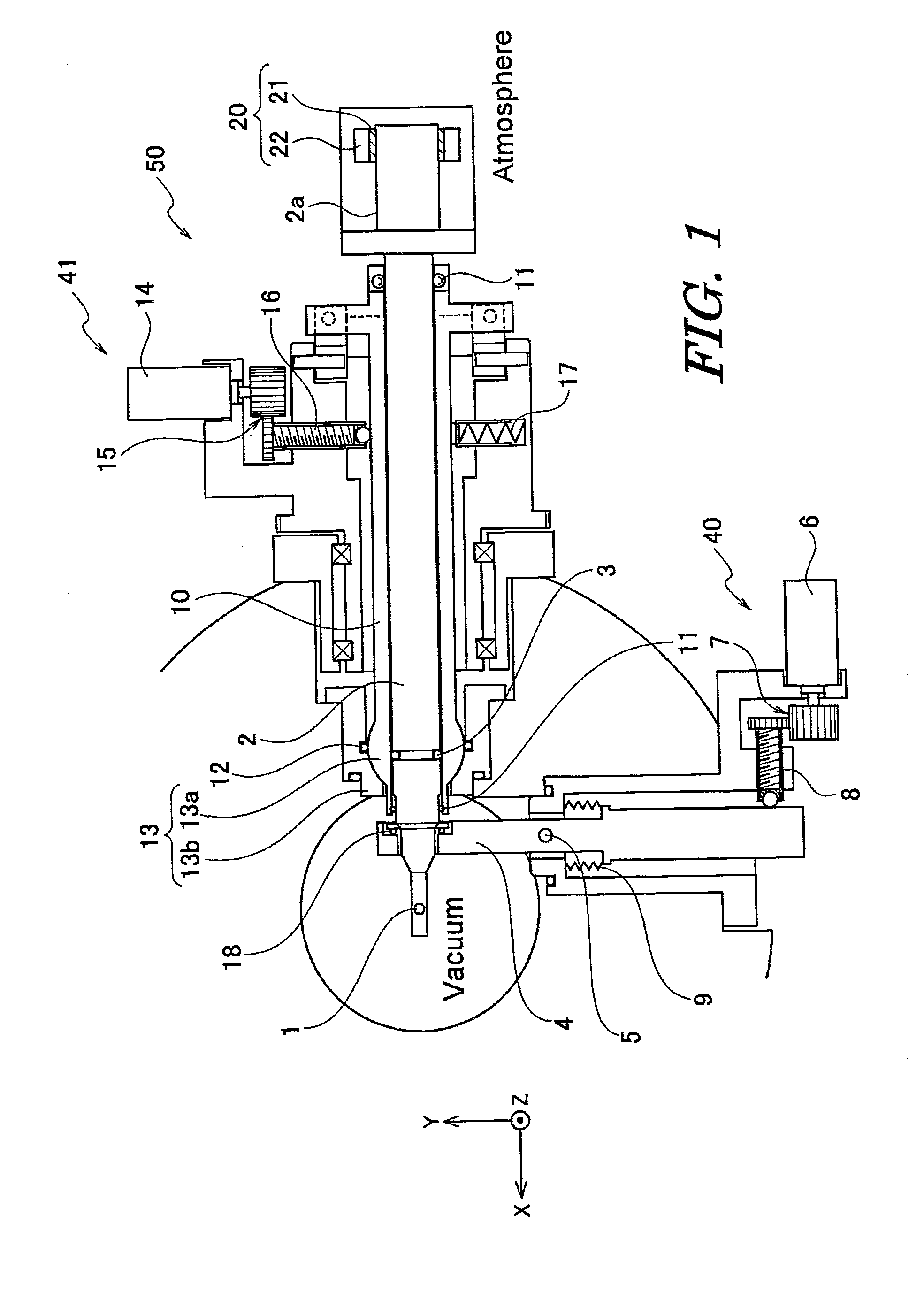
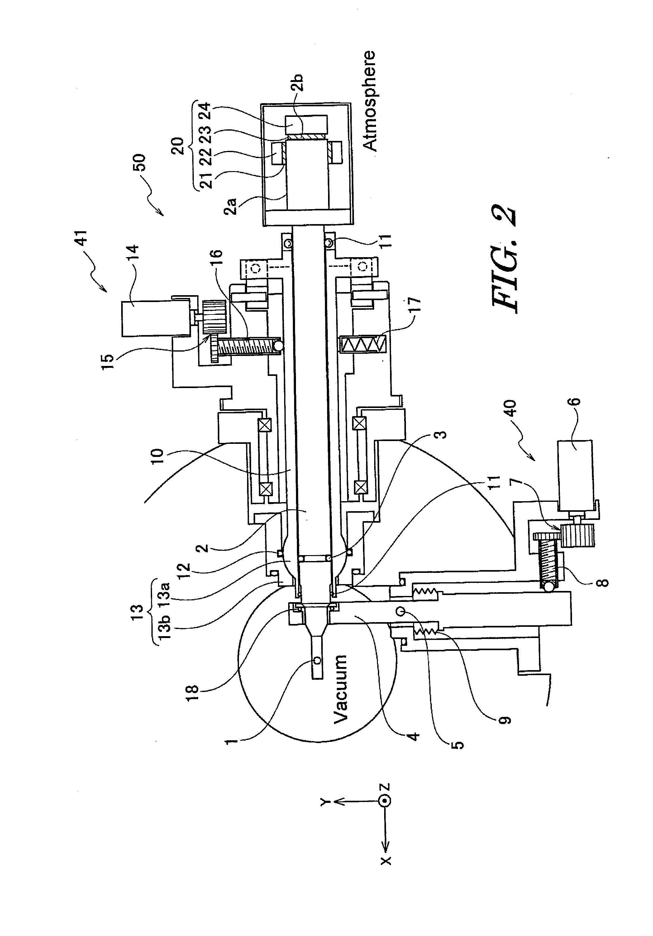
[0031]An embodiment of the present invention is described with reference to the accompanying drawings. An object-positioning device of the present embodiment that is described below is assumed to be mounted in an electron microscope, such as a transmission electron microscope, and to be used as a sample-positioning device that moves the sample. However, the object-positioning device of the present invention can be applied to a mechanism for use with any analysis instrument or observation instrument using a charged-particle beam to move an object over very short distances. The moved object is not limited to a sample. For example, the moved object includes a slit, an aperture, and so on.

[0032]FIG. 1 is a schematic view of a sample-positioning device associated with one embodiment of the present invention. In this figure, it is assumed that an electron beam (not shown) travels through a vacuum substantially parallel to the Z-axis and passes through a sample 1. The sample-positioning de...


PUM

PropertyMeasurementUnit
vibrational frequencyaaaaaaaaaa
operating frequencyaaaaaaaaaa
frequencyaaaaaaaaaa

Abstract

An object-positioning device comprises a rod-like object holder inserted in the chamber of a charged-particle beam system for moving the object outside the chamber, a support for slideably supporting at least a part of the side surface of the object holder, thus making the rear end of the holder outside the chamber a free end, and a vibration-absorbing portion mounted on the rear end of the object holder. The vibration-absorbing portion has an operating range in which vibrational frequencies in a translational direction perpendicular to the longitudinal direction of the object holder are absorbed. The natural vibrational frequency of the object holder in the bending mode is included within the operating range of the vibration-absorbing portion.

Description

BACKGROUND OF THE INVENTION[0001]1. Field of the Invention[0002]The present invention relates to an object-positioning device mounted in a charged-particle beam system.[0003]2. Description of Related Art[0004]Mechanical vibrations produced in an analytical instrument or observation instrument using a charged-particle beam (such as an electron microscope) create one of the main factors deteriorating a performance parameter of the instrument such as spatial resolution. Such vibrations are produced by various causes, and examples of the vibrations include vibrations of a building itself, noises around the instrument, and vibrations produced by a machine adjacent to the instrument.[0005]Various portions of the instrument are vibrated from these causes. The natural frequency of each portion of the instrument differs according to shape, material, weight, vibrational mode, and other factors.[0006]A goniometer having a sample holder for holding and moving a sample is disclosed in FIG. 11 of...

Claims


Application Information

Patent Timeline
Patent Type & Authority Applications(United States)
IPC IPC(8): G01N23/00
CPCG01N23/20016
Inventor HAMOCHI, MITSURU
Owner JEOL LTD
Why Eureka
Eureka Blog
Learn More