Hybrid braking system and method

Active Publication Date: 2010-06-03
GENERAL ELECTRIC CO
View PDF34 Cites 34 Cited by
  • Summary
  • Abstract
  • Description
  • Claims
  • Application Information

AI Technical Summary

Benefits of technology

[0005]Therefore there is a need

Problems solved by technology

Structural damage due to over-stressing the turbine blades and rotor can occur if the rotational speed of the wind turbine is allowed to increase without limit.
However, dynamic control and fast response are difficult to achieve in mechanical braking during operation of the turbine.
However, such mechanical braking approaches as discussed above have certain disadvantages.
All of these devices add significant cost and weight to the rotor blades and the overall drive train.
A

Method used


Image

  • Hybrid braking system and method
  • Hybrid braking system and method
  • Hybrid braking system and method

Examples


Embodiment Construction

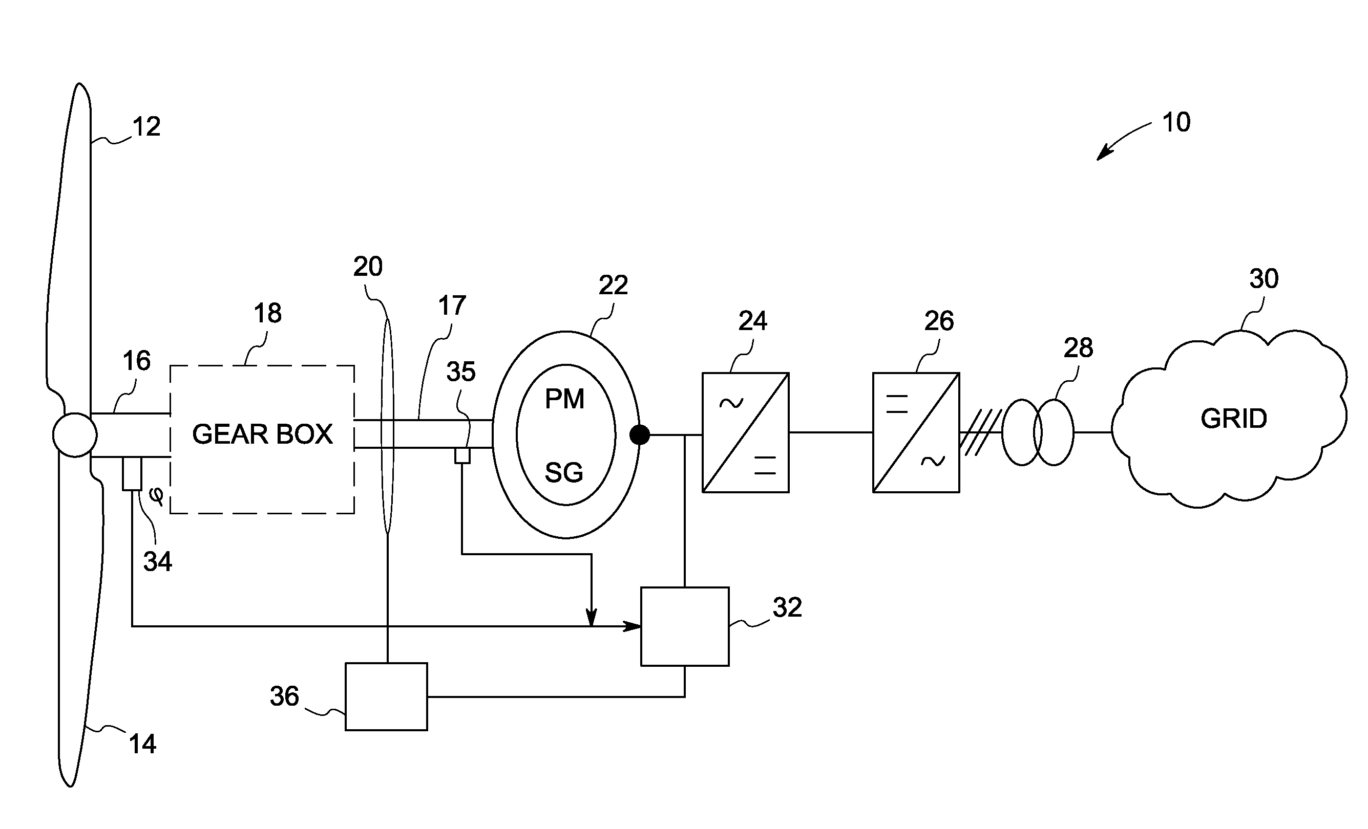
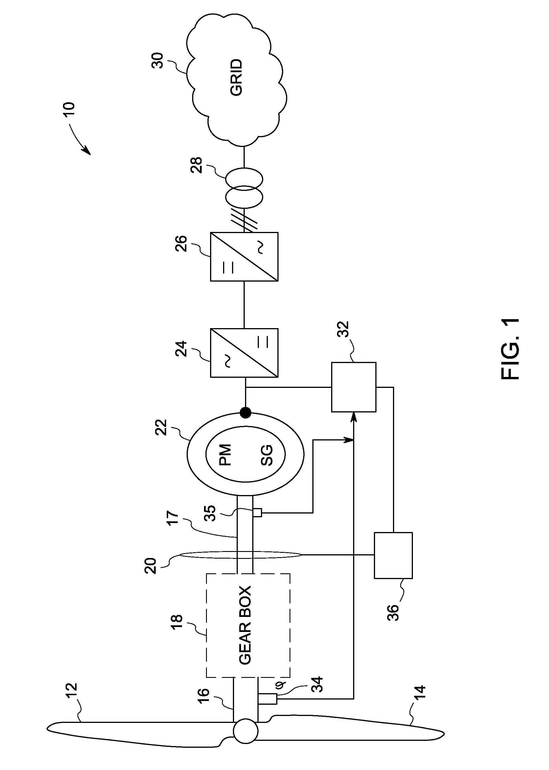
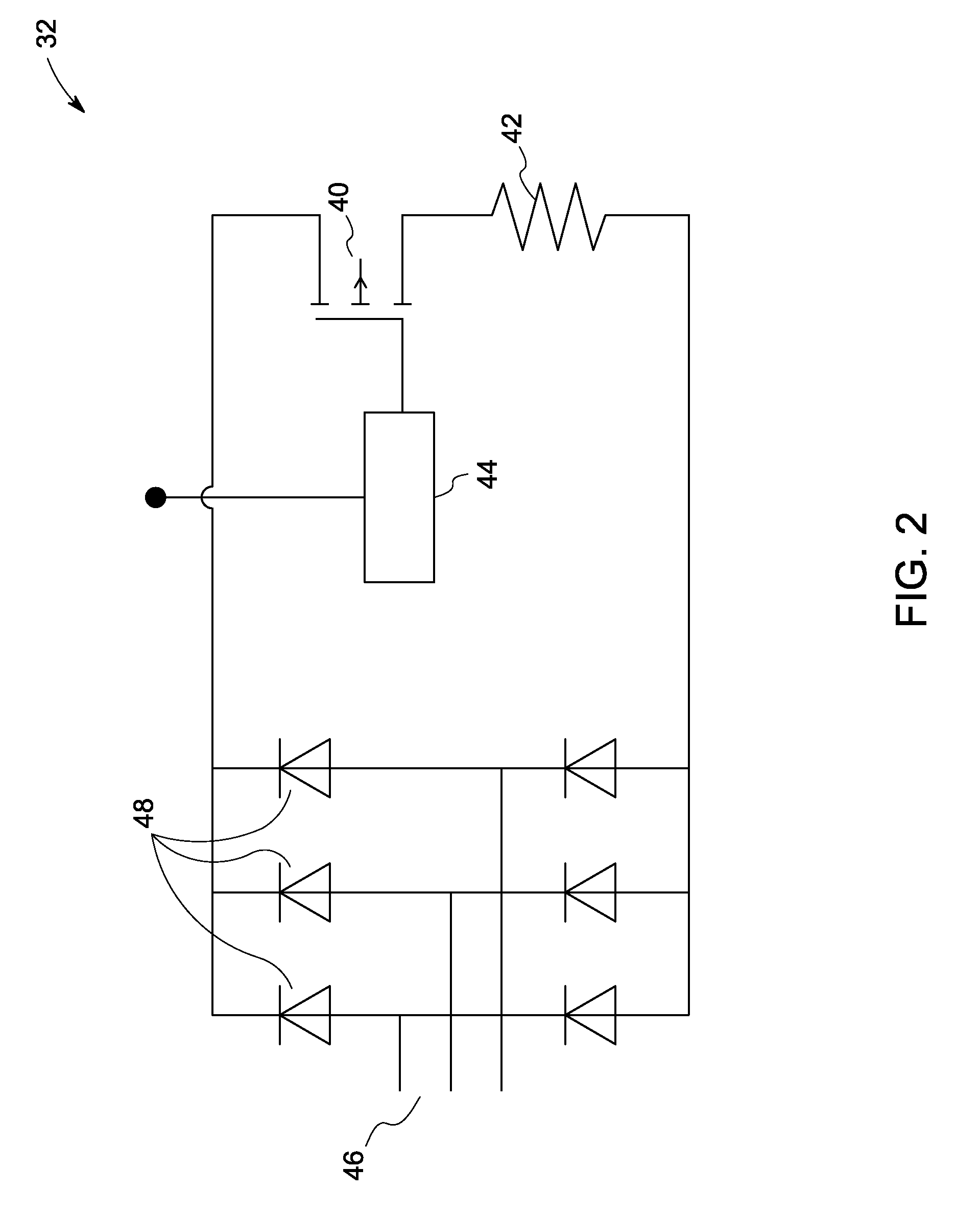
[0016]During operation of a wind turbine, various forces and moments induced by the wind act on the turbine's rotor shaft. For example, peak loads, sudden loading reversal, emergency stops, changing wind direction, and vibrations contribute to dynamic effect. One of the challenges in wind turbine design includes the turbine's overall dynamic stability. By considering only static conditions during design, life of drive train, gearbox and bearings in the wind turbines may be under-estimated. Many technical faults or grid events tend to trigger an emergency stop that results in sudden deceleration of the rotor that induces heavy loading on the wind turbine. Traditionally, mechanical brakes are applied in response to emergency stops. Such brakes induce braking torque to the system with limited controllability and time lag, thus inducing large dynamic torque components and overloads during emergency stop events. Furthermore, torsional oscillations with high torque amplitude are induced o...


PUM


Abstract

A wind turbine hybrid braking system is presented. The system includes a generator coupled to a main shaft of the wind turbine for generating and transmitting power. A mechanical brake is coupled to the main shaft for applying reaction torque upon braking of the wind turbine. The system further includes an electrical braking circuit coupled to the generator for acting in conjunction with the mechanical brake and dissipating active power via controlled switching.

Description

BACKGROUND[0001]The invention relates generally to braking in turbines and, in particular, to hybrid braking in wind turbines.[0002]Wind turbines have been used as a source of power for many years. Among the various operational parameters, speed control and emergency braking capability have particularly strong influences on the structural stability and longevity of the components within the wind turbine. Controlling the speed of a wind turbine rotor below its maximum limit is necessary in order to avoid the damaging effects of high velocity winds on the wind turbine and its supporting structure. Structural damage due to over-stressing the turbine blades and rotor can occur if the rotational speed of the wind turbine is allowed to increase without limit.[0003]Typically, mechanical braking systems in wind turbines are configured to halt the turbines during an emergency or any other event that requires stopping the turbine. However, dynamic control and fast response are difficult to ac...

Claims


Application Information

Patent Timeline
IPC IPC(8): H02P9/04F03D9/00F03D11/00F03D7/00H02P3/22H02K19/36
CPCF03D7/0248F03D7/0272H02P2101/15Y02E10/723Y02E10/725H02P9/102Y02E10/72
Inventor SCHRAMM, SIMON HERBERTSIHLER, CHRISTOF MARTIN
Owner GENERAL ELECTRIC CO
Why Eureka
Try Eureka