Energy Storage Systems

a technology of energy storage and energy storage, applied in the direction of superconducting magnets/coils, single ac network with different frequencies, dc source parallel operation, etc., can solve problems such as difficult to achieve in practi

Inactive Publication Date: 2010-06-03
ECOLE POLYTECHNIQUE FEDERALE DE LAUSANNE (EPFL)
View PDF4 Cites 102 Cited by
  • Summary
  • Abstract
  • Description
  • Claims
  • Application Information

AI Technical Summary

Problems solved by technology

Theoretical considerations make it desirable to compress and expand the gas under

Method used


Image

  • Energy Storage Systems
  • Energy Storage Systems
  • Energy Storage Systems

Examples


Embodiment Construction

[0046]A list of the articles referred to in Sections 1, 2 and 3 of the detailed description is provided at the end of the description.

[0047]1. Compression / Expansion System for an Energy Storage System

[0048]A hybrid energy storage system has been described in [1] and [2], preferably used in the context of storing electrical energy produced from renewable sources as photovoltaic panels or wind turbines.

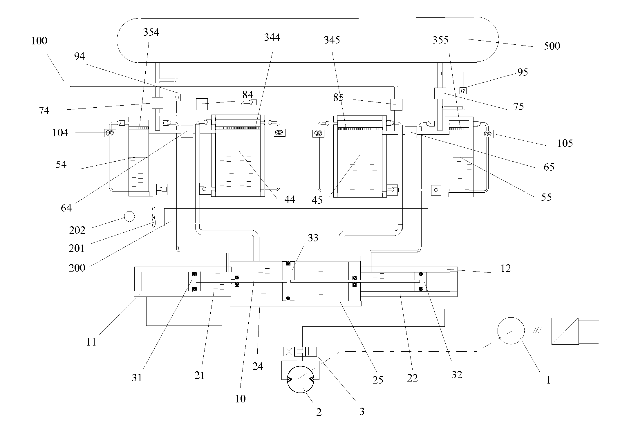
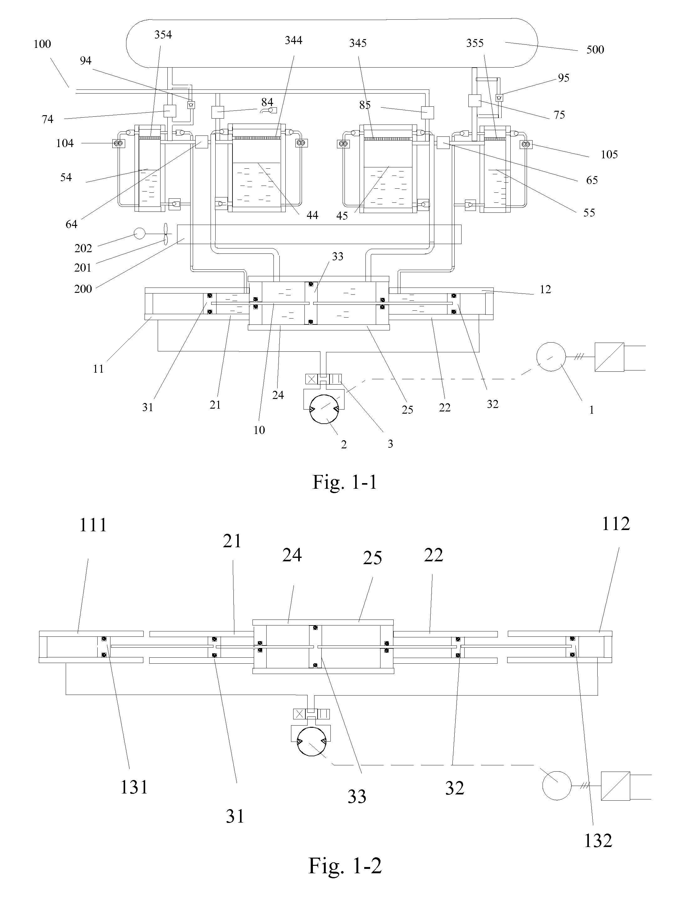
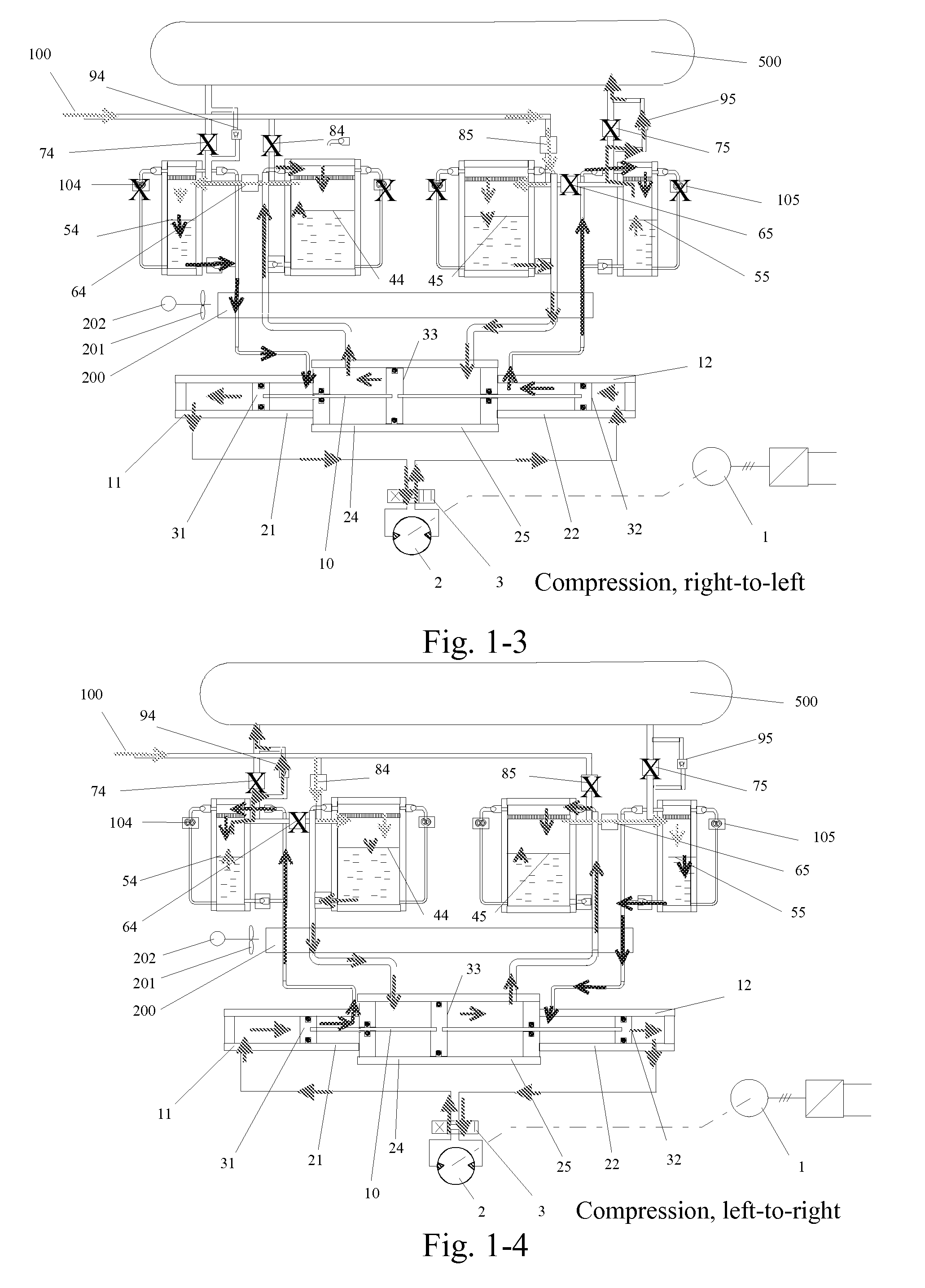
[0049]The first main inventive aspect of the present invention relates to a compression / expansion apparatus used to convert electric energy in mechanical / thermal energy. The system is composed of an electric motor / generator coupled to a hydraulic pump / motor, from where the generated liquid pressure is injected in a cylinder system where the liquid pressure is transmitted to the air-compression chambers, where the air pressure is obtained from a so-called liquid piston principle.

[0050]Accumulating energy corresponds to the compression phase of the air, and the restoring energy correspond...


PUM


Abstract

Different types of energy storage systems are described, in particular hydro-pneumatic storage systems. In one, energy is stored by compressing gas in a chamber (44,45,54,55) with a liquid piston and released by gas expansion. A spray head or grid at the top of the chamber (44,45,54,55) supplies liquid as a shower through the gas being compressed or expanding in the cylinder (11,12) to maintain an isothermal condition. In another, energy is stored from an array of solar cells connected to an array of supercapacitors forming an auxiliary storage, and a main energy storage device such as a hydro-pneumatic storage system, for supply to an AC or DC network. The efficiency is improved by connecting the solar cells via the array of supercapacitors to the AC or DC network. An immersed hydro-pneumatic storage device for off-shore/on-shore power generation systems comprises a cylinder that is immersed in a liquid mass, wherein energy is stored by compressing gas with a liquid piston and energy is released by gas expansion. The mass of liquid maintains an isothermal condition in the cylinder during compression and expansion.

Description

FIELD OF THE INVENTION[0001]This invention relates to energy storage systems particularly in the context of distributed and intermittent renewable energy sources such as solar and wind.BACKGROUND OF THE INVENTION[0002]The increasing recourse to renewable energy sources such as solar and wind has led to a need to store the produced energy. For this, hydro-pneumatic storage systems have been developed wherein energy is stored by compressing a gas and is released by gas expansion.[0003]In order to provide good power quality and flexibility to these storage systems, it has been proposed to associate a main storage system (in particular a hydro-pneumatic storage system) with an auxiliary, supercapacitive storage system. Power variation is achieved by intermittent operation of the main storage system and use of the supercapacitive storage system to smooth the resulting power, through the regulation of a common DC bus voltage. Such hybrid storage systems are compatible with a wide range of...

Claims


Application Information

Patent Timeline
IPC IPC(8): H02J1/12F03B17/02F03G7/00F03B13/06F03D9/00H01L39/00
CPCF02C6/16F03D9/028F03G6/001F05B2210/18Y02E10/72Y02E60/15Y02E60/17Y02E70/30Y02E10/46H02J3/28H02J15/006H02J7/345H02J7/35F03D9/17Y10T137/2931F03D9/255F03D13/25F03D9/28F03D9/007H02J2300/28H02J2300/26H02J2300/24H02J3/381Y02E10/56Y02E10/76Y02E60/16
Inventor RUFER, ALFREDFAVRAT, DANIELBARRADE, PHILIPPELEMOFOUET, SYLVAIN
Owner ECOLE POLYTECHNIQUE FEDERALE DE LAUSANNE (EPFL)
Why Eureka
Try Eureka