Image processing system

a processing system and image technology, applied in the field of image processing, can solve the problems of flickering or wobble, and achieve the effect of reducing inaccuracy

Inactive Publication Date: 2010-06-03
SONY CORP
View PDF9 Cites 46 Cited by
  • Summary
  • Abstract
  • Description
  • Claims
  • Application Information

AI Technical Summary

Benefits of technology

[0010]This embodiment can reduce inaccuracies in the estimated light direction in the situation in which the reference the luminance across the surface of the reference object is saturated or partly saturated.

Problems solved by technology

If a computer generated object is rendering a computer generated object in real time in accordance with this changing direction of light, then this may manifest itself as an undesirable flickering or “wobble”.

Method used


Image

  • Image processing system
  • Image processing system
  • Image processing system

Examples


Embodiment Construction

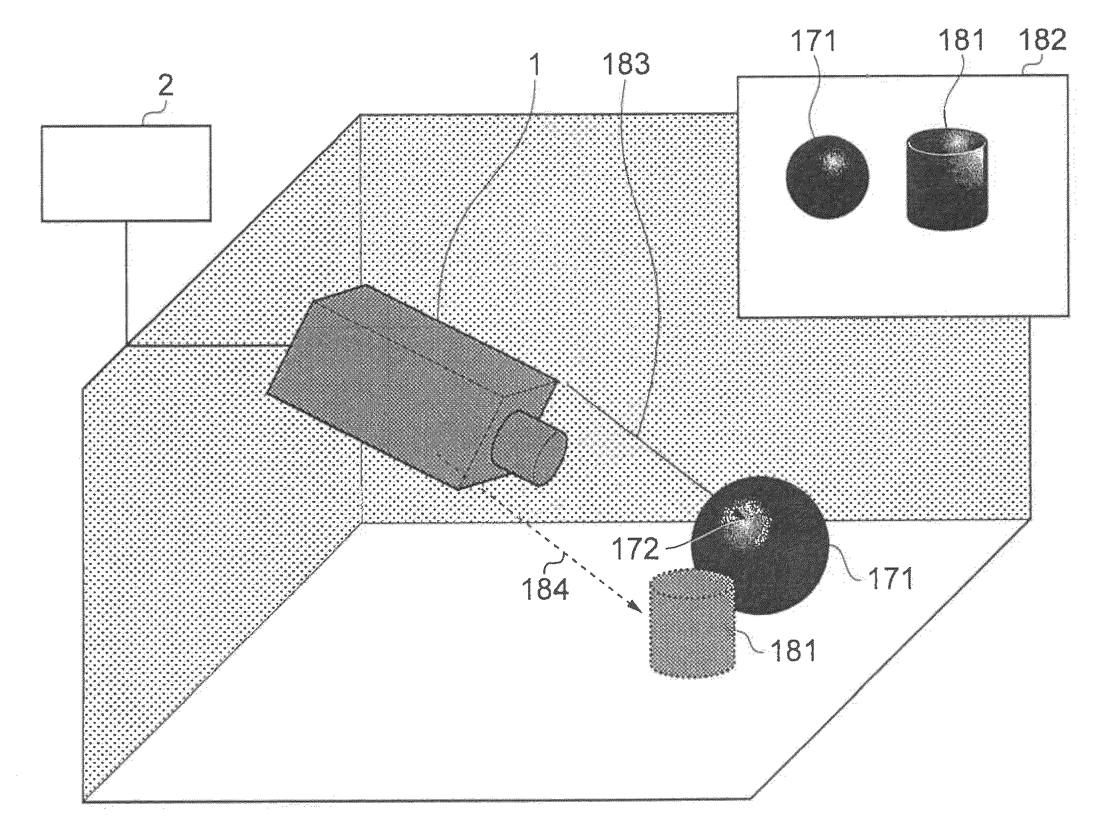
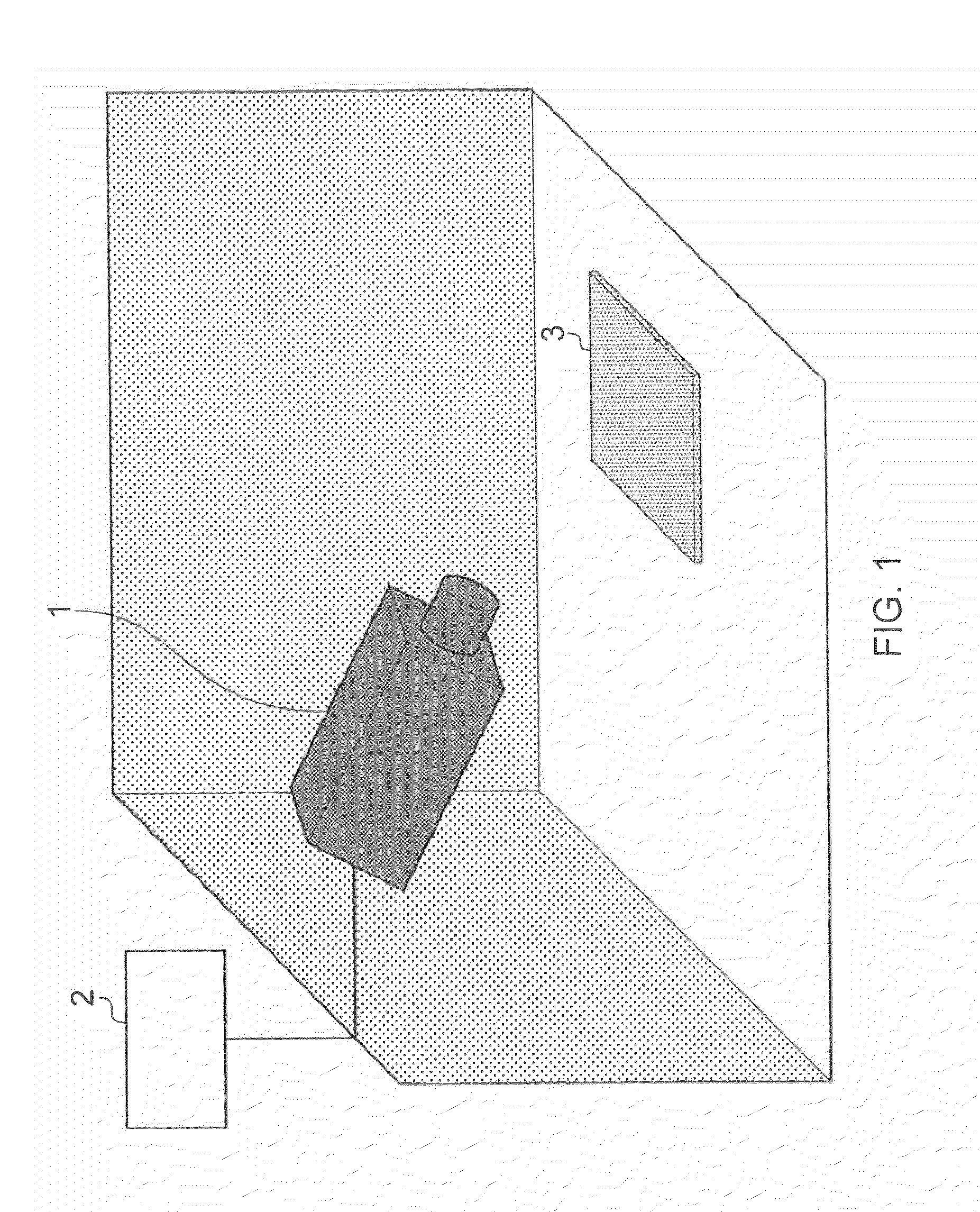
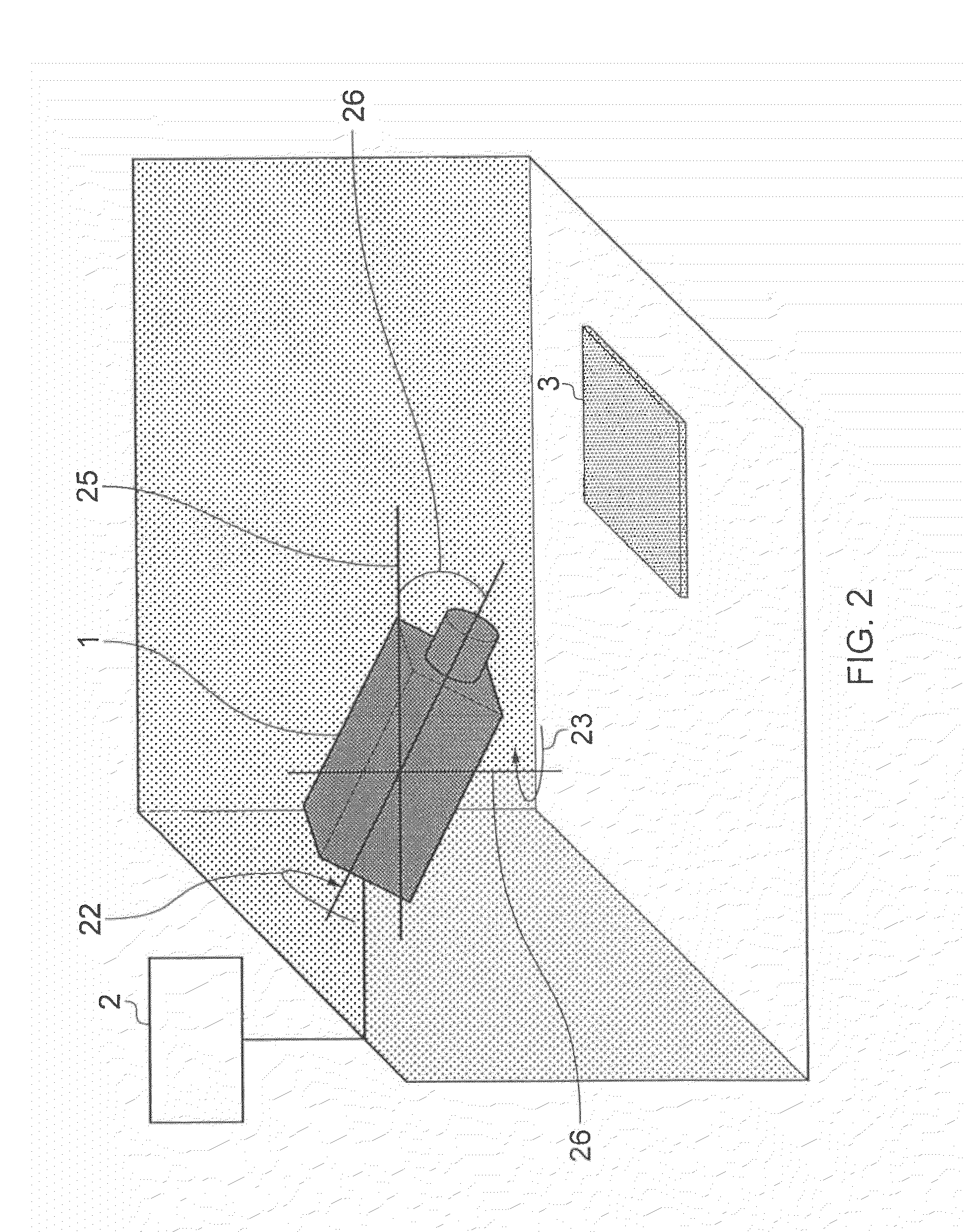
[0042]FIG. 1 provides a schematic diagram of an example of a system for determining camera parameters from a captured image. A camera apparatus 1 is provided which is capable of capturing image data, for example a video signal, representative of a scene as viewed by the camera 1. The camera 1 is connected to an image processor 2. Together the camera 1 and image processor 2 comprise an image processing apparatus. The camera is directed at a calibration surface 3. The camera 1 captures image data representative of the calibration surface 3 and communicates data corresponding to these images back to the image processor 2. The calibration surface 3 includes a calibration pattern. The image processor 2 analyses the images captured by the camera 1 of the calibration surface and uses information derived from the captured images of the calibration surface 3 to determine a set of parameters corresponding to the orientation of the camera 1 relative to the calibration surface 3.

[0043]FIG. 2 il...


PUM


Abstract

A computer graphics generation system combines video images of a scene captured by a camera with one or more rendered computer generated objects. The system comprises a camera which is arranged to generate an image signal representative of a scene including a reference object of a predetermined shape, and an image processor. The image processor is arranged in operation to identify the reference object from the image signal, to detect a luminance distribution across a surface of the reference object by estimating a luminance magnitude at a plurality of surface points on the surface of the reference object, and to estimate a direction of light incident on the reference object derived from the detected luminance distribution across the surface of the reference object by calculating the average of a plurality of luminance vectors, each luminance vector corresponding to one of the surface points and comprising a luminance magnitude of the corresponding surface point and a luminance direction corresponding to a direction perpendicular to the surface at the corresponding surface point, wherein the luminance distribution across the surface of the reference object is detected for luminance above a threshold clipping level. Accordingly a reduction in the “wobble” of the computer generated objects in the scene can be achieved and a more stable image provided from the image light direction estimation.

Description

FIELD OF THE INVENTION[0001]The present invention relates to image processing. More particularly embodiments of the present invention relate to methods of and systems for estimating camera parameters from a captured image.BACKGROUND OF THE INVENTION[0002]In many applications it is desirable to add computer generated graphics to enhance conventionally captured video images. For example, news broadcasts and televised weather forecasts frequently include computer generated content such as text banners, maps, backdrops and so on, which are added to conventionally captured video images of a human presenter. Such computer generated content can improve the clarity with which information is presented to a viewer and can be easily and conveniently edited and updated. Similarly, many modern films include a great deal of computer generated content which is intermixed with real-life actors and objects to achieve effects which would be impossible or very expensive to achieve in real life.[0003]I...

Claims


Application Information

Patent Timeline
Patent Type & Authority Applications(United States)
IPC IPC(8): H04N9/74G06T15/50
CPCG06K9/00228G06T2207/30204G06T15/506G06T7/0018G06T7/80G06V40/161G06T7/00G06V10/60
Inventor MORIWAKE, KATSUAKIRA
Owner SONY CORP
Why Eureka
Try Eureka