Image Display Device and Production Method Thereof

Inactive Publication Date: 2010-06-03
DEXERIALS CORP
View PDF25 Cites 16 Cited by
  • Summary
  • Abstract
  • Description
  • Claims
  • Application Information

AI Technical Summary

Benefits of technology

[0018]As described above, when the size of the protective panel is larger than the size of the image display panel, the occurrence of warping at the peripheral edge of the protective panel is pronounced. Therefore, in the first image display device or the method for producing the same according to the present invention, the resin composition is cured by UV-ray irradiation in a state where the peripheral edge of the protective panel is fixed using a fixing jig, and the peripheral edge is also fixed with the fixing jig even after the curing. Consequently, the resin composition can be cured in a state where warping of the protective panel is corrected, and a state in which the protective panel is not warped can be maintained.
[0019]On the other hand, in the second image display device or the second method for producing the same according to the present invention, the focus is on the size of the protective panel, the size of the image display panel, and the size of the case thereof. The resin composition is cured in a state where the outer dimension of the protective panel, the outer dimension of the image display panel, and the inner dimension of the case thereof are made substantially equal. Then, the resin composition is cured in a state where substantially the whole face of the protective panel is in contact with the resin composition. Consequently, the resin curing are not carried out in a state where the peripheral edge of the protective panel is open. In addition, just by fitting the protective panel and the image display panel in the case with the resin composition interposed therebetween, warping upwards of the protective panel can be suppressed from the side face (face in contact with the case) of the protective panel. Consequently, the resin can be uniformly cured over the whole face of the protective panel without having to take any particular fixing measures for the protective panel, and the occurrence of warping can be suppressed.
[0020]The conventional art completely fails to describe the idea of suppressing the occurrence of warping in the protective panel by making the outer dime

Problems solved by technology

However, when such a configuration is employed, the gap between the image display panel and the protective panel scatters light, resulting in decreased contrast and luminance.
This leads to the problem that image quality is harmed.

Method used


Image

  • Image Display Device and Production Method Thereof
  • Image Display Device and Production Method Thereof
  • Image Display Device and Production Method Thereof

Examples


Example

Example 1

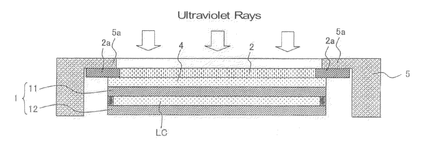
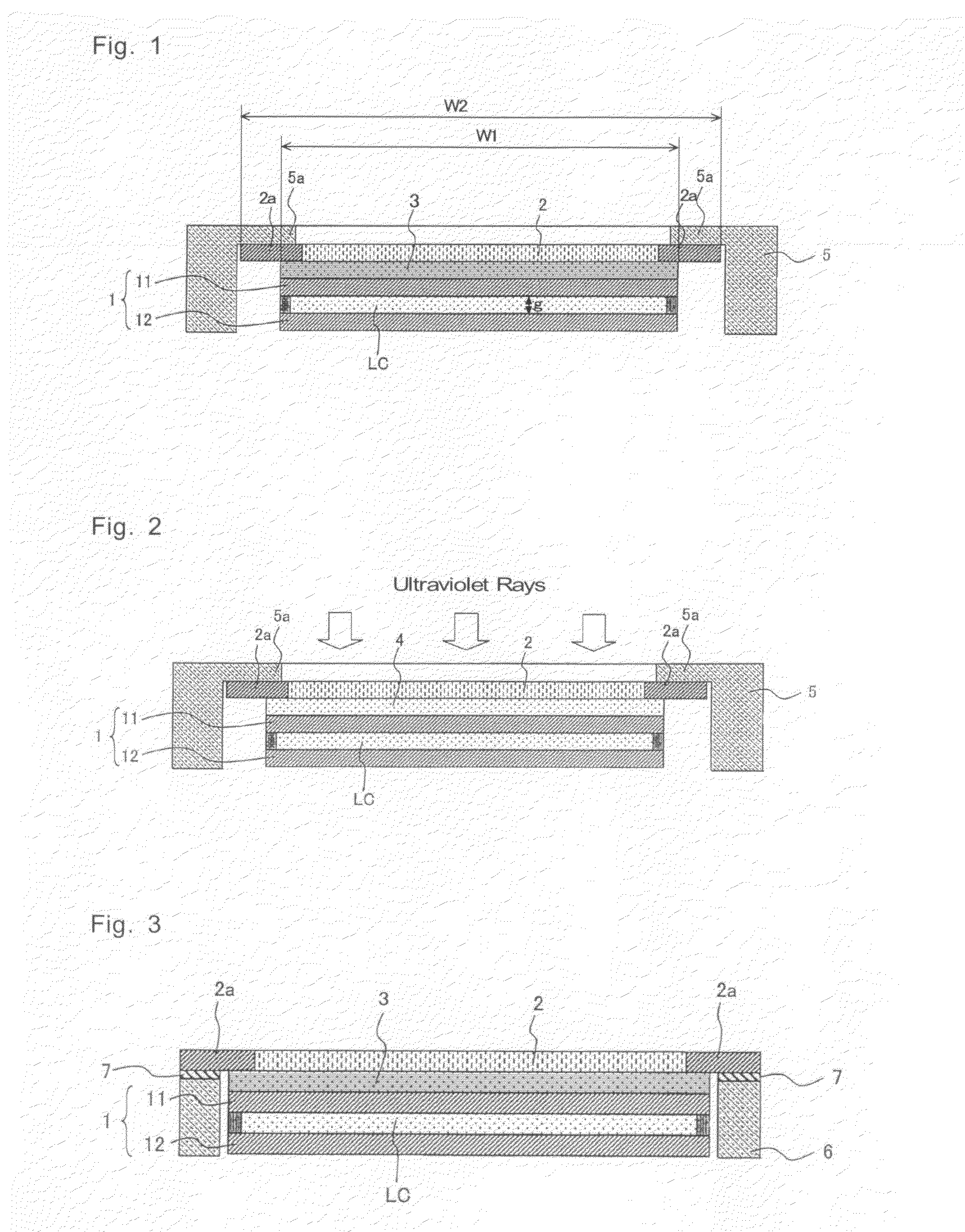
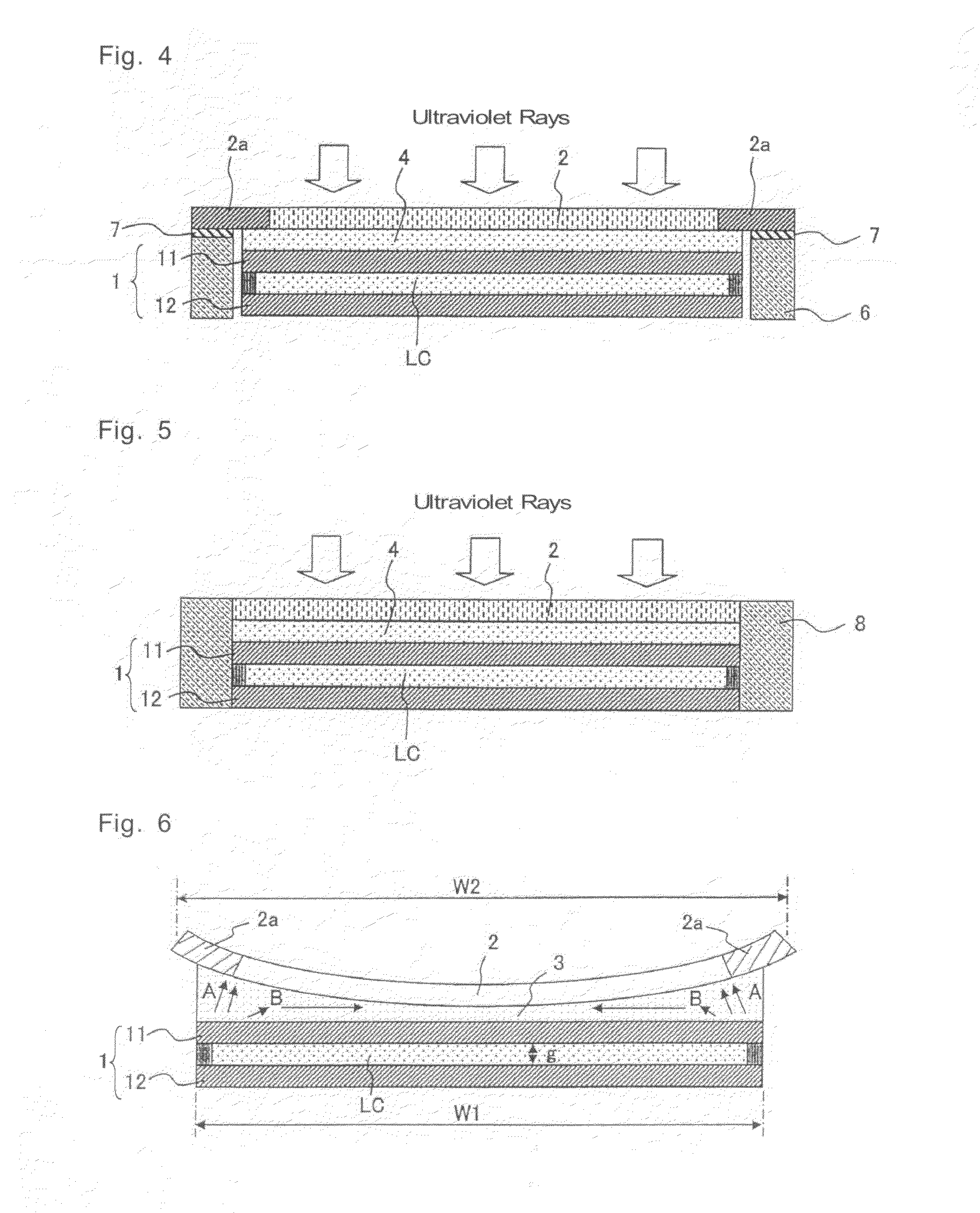
[0065]A protective panel was pasted on a liquid crystal display panel according to the method illustrated in FIG. 2 to produce a liquid crystal display device. The used protective panel was a transparent plastic panel formed from polymethyl methacrylate (PMMA). A case housing the liquid crystal display panel was used as a fixing jig. An upper face of a light shielding part formed on a peripheral edge of the protective panel was held and fixed with forming an eaves-shaped holding part on this case.

[0066]The resin composition to be arranged between the liquid crystal display panel and the protective panel was prepared by kneading in a kneader 70 parts by weight of an ester compound formed from a maleic anhydride adduct of a polyisoprene polymer and 2-hydroxyethyl methacrylate, 30 parts by weight of dicyclopentenyl oxyethyl methacrylate, 10 parts by weight of 2-hydroxybutyl methacrylate, 30 parts by weight of a hydrogenated terpene resin, 140 parts by weight of a butadiene pol...

Example

Example 2

[0072]A liquid crystal display device was produced in the same manner as in Example 1, except that the resin composition to be arranged between the liquid crystal display panel and the protective panel was changed as follows. In the present example too, a liquid crystal display device could be obtained which had hardly any warping of the protective panel, no display unevenness, and excellent outdoor visibility and impact resistance.

[0073]More specifically, the resin composition in the present example was prepared by kneading in a kneader 100 parts by weight of an ester compound formed from a maleic anhydride adduct of a polyisoprene polymer and 2-hydroxyethyl methacrylate, 30 parts by weight of dicyclopentenyl oxyethyl methacrylate, 10 parts by weight of 2-hydroxybutyl methacrylate, 30 parts by weight of a hydrogenated terpene resin, 210 parts by weight of a butadiene polymer, 7 parts by weight of a photopolymerization initiator, and 1.5 parts by weight of a visible region ...

Example

Example 3

[0075]A liquid crystal display device was produced in the same manner as in Example 1, except that the resin composition to be arranged between the liquid crystal display panel and the protective panel was changed as follows. In the present example too, a liquid crystal display device could be obtained which had hardly any warping of the protective panel, no display unevenness, and excellent outdoor visibility and impact resistance.

[0076]More specifically, the resin composition in the present example was prepared by kneading in a kneader 70 parts by weight of an ester compound formed from a maleic anhydride adduct of a polyisoprene polymer and 2-hydroxyethyl methacrylate (trade name: UC-203, manufactured by Kuraray Co., Ltd.), 30 parts by weight of dicyclopentenyl oxyethyl methacrylate (trade name: FA512M, manufactured by Hitachi Chemical Co., Ltd.), 10 parts by weight of 2-hydroxybutyl methacrylate (trade name: Light Ester HOB, manufactured by Kyoeisha Chemical Co., Ltd.),...


PUM


Abstract

An image display device, and a production method thereof are provided, which are capable of suppressing warping of a protective panel formed from a plastic as much as possible. In an image display device having a liquid crystal display panel 1 and a transparent protective panel 2 formed from a plastic which are arranged facing each other via a cured resin, an outer dimension of the protective panel 2 is made larger than an outer dimension of the liquid crystal display panel 1, curing of a resin composition 4 is carried out in a state where a peripheral edge of the protective panel 2 is fixed with a fixing jig 5, and the peripheral edge of the protective panel 2 is fixed with the fixing jig 5 even after the curing of the resin composition 4. Alternatively, the outer dimension of the protective panel 2 is substantially equal to an outer dimension of the liquid crystal display panel 1, this outer dimension is substantially equal to an inner dimension of a case 8 of the liquid crystal display panel 1 and the protective panel 2, and the curing of the resin composition 4 is carried out in a state where the resin composition 4 is in contact with substantially the whole face of the protective panel 2.

Description

TECHNICAL FIELD[0001]The present invention relates to an image display device having an image display panel such as a liquid crystal display panel, and a method for producing such an image display device. More specifically, the present invention relates to an improved image display device, and production method thereof, in which a cured resin is arranged between an image display panel and a transparent protective panel.BACKGROUND ART[0002]In an image display device such as a liquid crystal display device, to prevent the image display panel from being damaged and to protect the surface thereof, a transparent protective panel such as a glass panel or a plastic panel is arranged on the front face of the image display panel. More specifically, for example, the protective panel is mounted inside a case with a slight gap with respect to the image display panel, by arranging a spacer or the like between the image display panel and the protective panel at the peripheral edge of the image di...

Claims


Application Information

Patent Timeline
IPC IPC(8): G02F1/1333H01J9/20
CPCG02F1/133308G02F2001/133311G02F2001/13332G02F2001/133325G02F1/1333G02F2201/50G02F2201/503G02F2201/54G02F2202/28G02F2001/133331G02F1/133311G02F1/13332G02F1/133325G02F1/133331G09F9/00
Inventor TOYODA, TOMOYUKISHINYA, YOSHIHISAKAMATA, YUSUKE
Owner DEXERIALS CORP
Why Eureka
Try Eureka