
Progressive-power lens

a technology of progressive power and lens, applied in the field of progressive power lenses, can solve problems such as degrading optical performance, and achieve the effect of minimizing the degradation of optical performance due to the shallower base curv

Active Publication Date: 2010-06-03
EHS LENS PHILIPPINES
View PDF9 Cites 4 Cited by
  • Summary
  • Abstract
  • Description
  • Claims
  • Application Information

AI Technical Summary

Benefits of technology

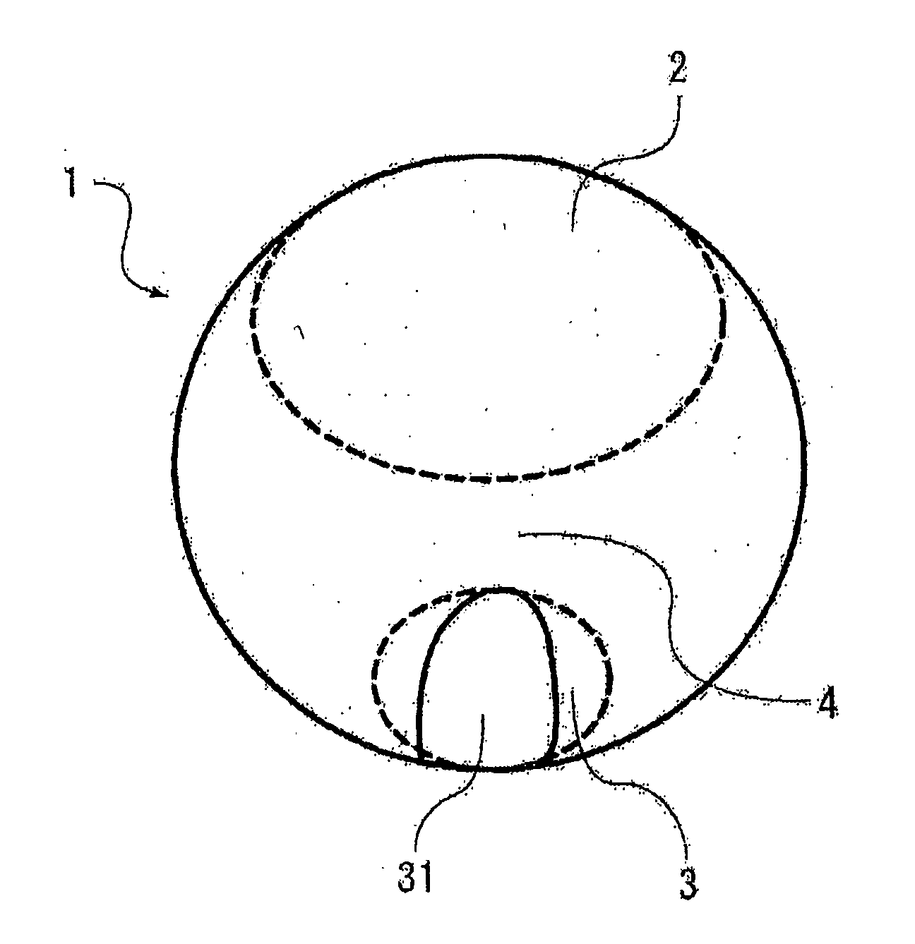
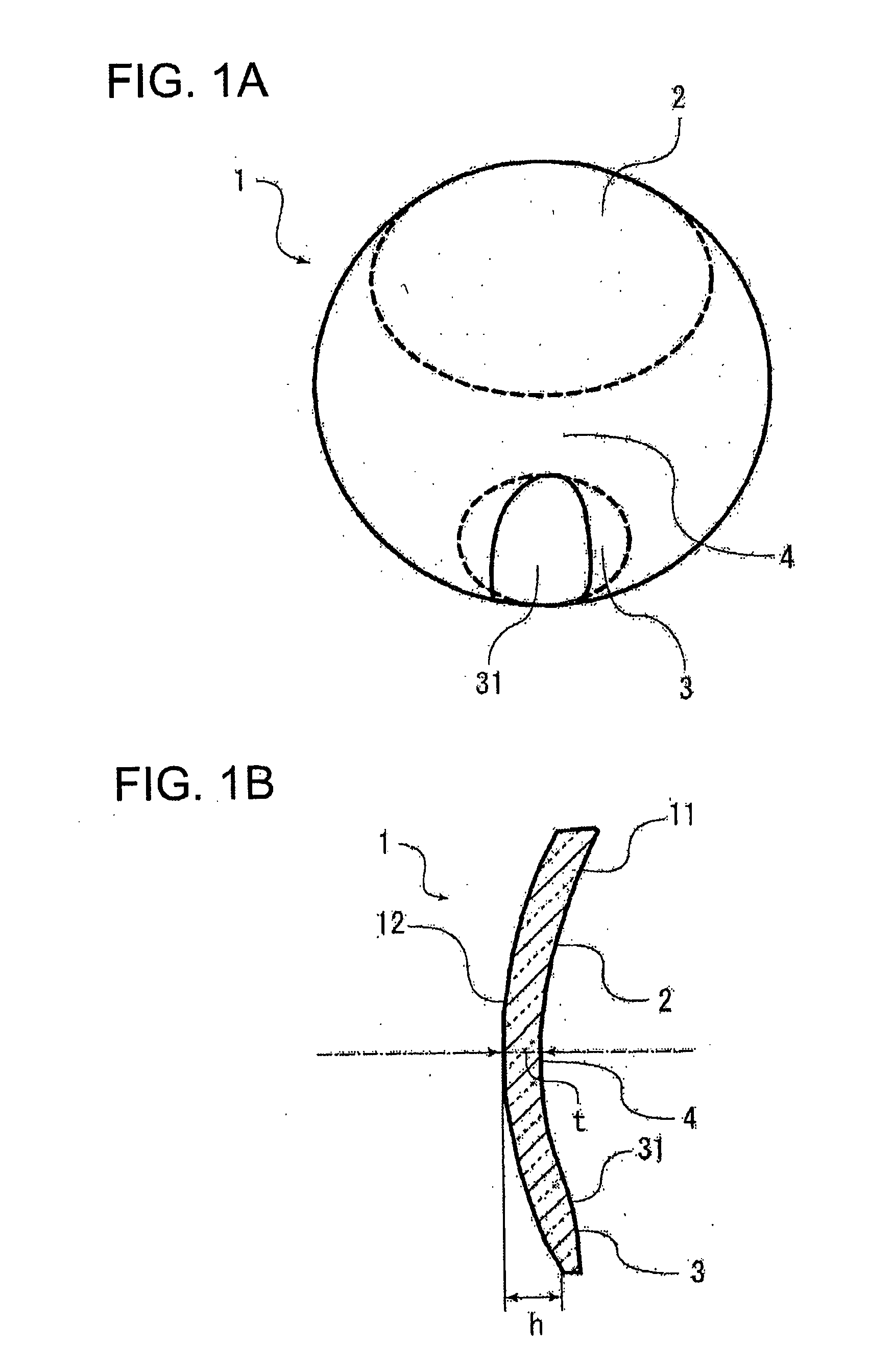
[0010]The back surface progressive-power lens is configured such that a region of the near portion of the eye-side refractive surface is provided with the convex region, which is convex to the eye. The provision of the convex region in the near portion allows the eye-side distance portion to be a small-curvature concave surface for providing a predetermined addition power, as well as allows the curvature of the object-side refractive surface providing power required for the distance portion to be small in accordance with the eye-side small curvature. Therefore, the provision of the convex region in the near portion results in a shallow base curve, thereby providing a thin lens with excellent exterior appearance.
[0012]The provision of the convex region in the near portion allows a back surface progressive-power lens with better exterior appearance and reduced thickness. There is a drawback, however, that the shallower base curve increases astigmatism and hence degrades optical performance. The drawback can be overcome by advances in design technology. This application can minimize such optical performance degradation by limiting the degree of convexity of the convex region as well.

Problems solved by technology

There is a drawback, however, that the shallower base curve increases astigmatism and hence degrades optical performance.

Method used


Image

  • Progressive-power lens
  • Progressive-power lens
  • Progressive-power lens

Examples


example 1

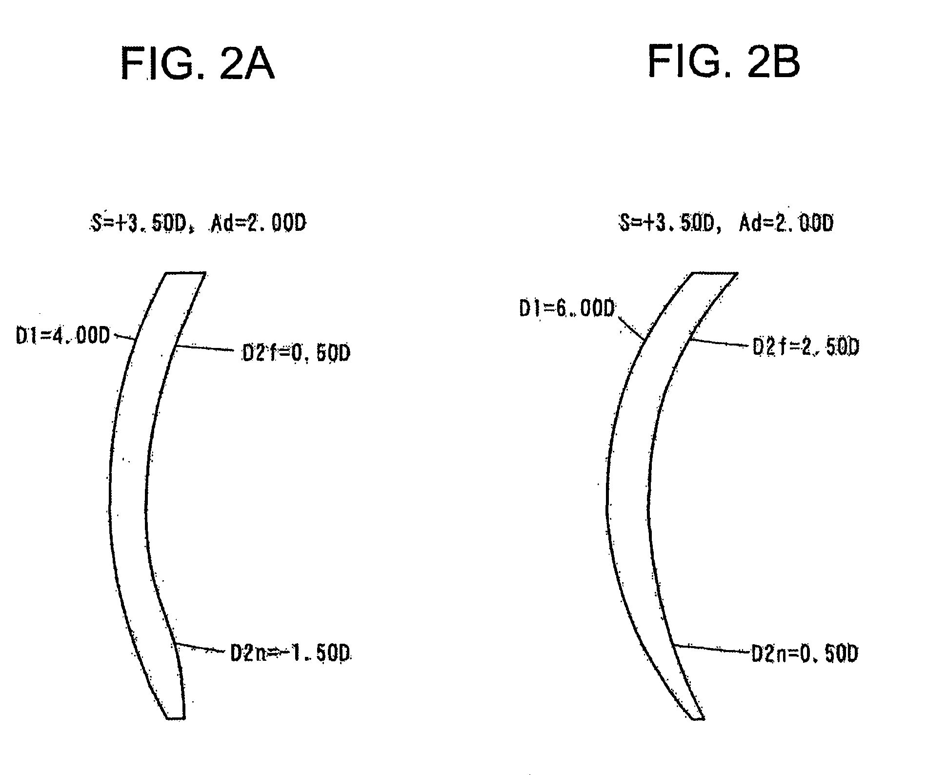
[0056]A back surface progressive-power lens was designed in the following conditions: surface power of distance portion D2f is 1.00 D; surface power of near portion D2n is −1.00 D; addition power Ad is 2.00 D; power of distance portion S is 3.50 D; power of the object-side refractive surface (base curve) D1 is 4.50 D; and the near portion on the eye-side refractive surface was provided with a convex region that protrudes toward the eye. The refractive index of the lens material was 1.66. The lens material with this same refractive index was used in all the following Examples and Comparison Example. In this design, the near portion of a conventional, entirely concave back surface progressive-power lens was simply provided with the convex region and the increased astigmatism due to the shallower base curve was not corrected.

[0057]In this design, provided that the lens is circular with a diameter of 70 mm and a line connecting the geometrical centers of the object-side and eye-side ref...

example 2

[0060]A back surface progressive-power lens was designed in the following conditions: surface power of distance portion D2f is 1.00 D; surface power of near portion D2n is 1.00 D; addition power Ad is 2.00 D; Power of distance portion S is 3.50 D; power of the object-side refractive surface (base curve) D1 is 4.50 D; and the near portion of the eye-side refractive surface was provided with a convex region that protrudes toward the eye. In this design, an aspherical surface was added to correct the increased astigmatism due to the shallower base curve.

[0061]In this design, provided that the lens is circular with a diameter of 70 mm, the overhang h that is the distance in the center line direction between the geometrical center of the object-side refractive surface and the outer edge of the object-side refractive surface was 4.2 mm, and the center thickness t was 4.1 mm. Since the aspherical surface was added, the center thickness t was thinner than that of Example 1 by 0.3 mm.

[0062]F...


PUM


Abstract

An eye-side refractive surface 11 of a distance portion is concave and at least part of an eye-side refractive surface 3 of a near portion is a convex region 31 where one or both of principal meridians of the surface are convex. This provides a back surface progressive-power lens capable of solving disadvantages in terms of lens thickness, external appearance and the like in a back surface progressive-power lens in which the eye-side refractive surface is formed of a progressive-power surface.

Description

TECHNICAL FIELD [0001]The present invention relates to a progressive-power lens mainly used for presbyopia correcting glasses.BACKGROUND ART [0002]A progressive-power lens includes two viewing zones, each having different power, and one viewing zone therebetween where the power progressively changes. These viewing zones have no boundaries, thereby providing excellent exterior appearance and multiple viewing zones in a single lens, each having different power. For these reasons, a progressive-power lens is frequently used as a spectacle lens with accommodation correction capability such as presbyopia.[0003]FIG. 3 shows a general construction of a progressive-power lens. FIG. 3(a) is a front view and FIG. 3(b) is a longitudinal cross-sectional view. The progressive-power lens 100 includes an upper distance portion 2 that is a viewing zone for viewing relatively distant objects and a near portion 3 that is located below the distance portion 2 and has different power from that of the di...

Claims


Application Information

Patent Timeline
Patent Type & Authority Applications(United States)
IPC IPC(8): G02C7/06
CPCG02C7/068G02C7/061G02B3/10
Inventor KAGA, TADASHISHINOHARA, TOSHIHIDE
Owner EHS LENS PHILIPPINES
Learn More